
Fixed type electrode tip removal device

A technology for dismantling devices and electrode heads, which is applied in the direction of auxiliary devices, electrode features, resistance welding equipment, etc., can solve the problems that the electrode head requires physical strength, cannot realize labor saving and complete automation, and achieves the effect of labor saving and reliable disassembly

Inactive Publication Date: 2005-02-09
OHARA
View PDF1 Cites 9 Cited by
  • Summary
  • Abstract
  • Description
  • Claims
  • Application Information

AI Technical Summary

Problems solved by technology

Therefore, dismantling the electrode head requires physical strength, which cannot be labor-saving and fully automated.

Method used


Image

  • Fixed type electrode tip removal device
  • Fixed type electrode tip removal device
  • Fixed type electrode tip removal device

Examples


no. 1 example

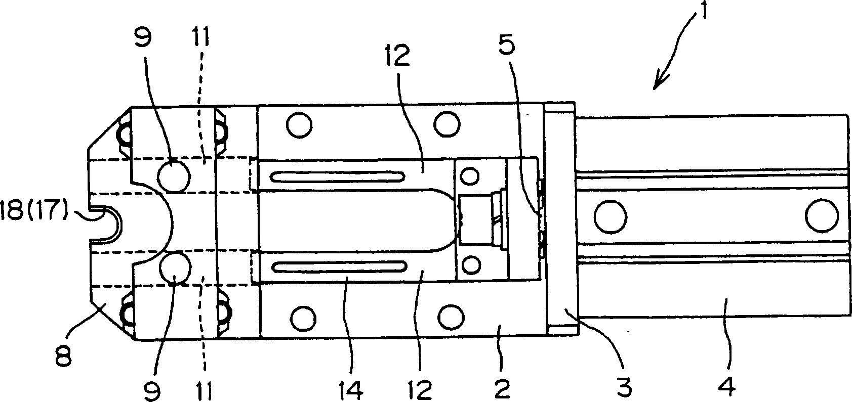
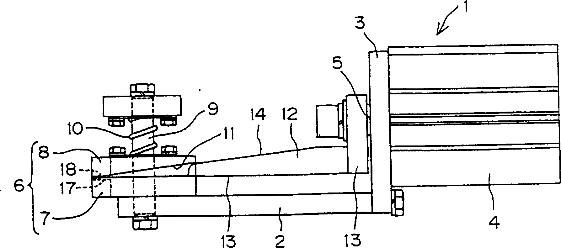
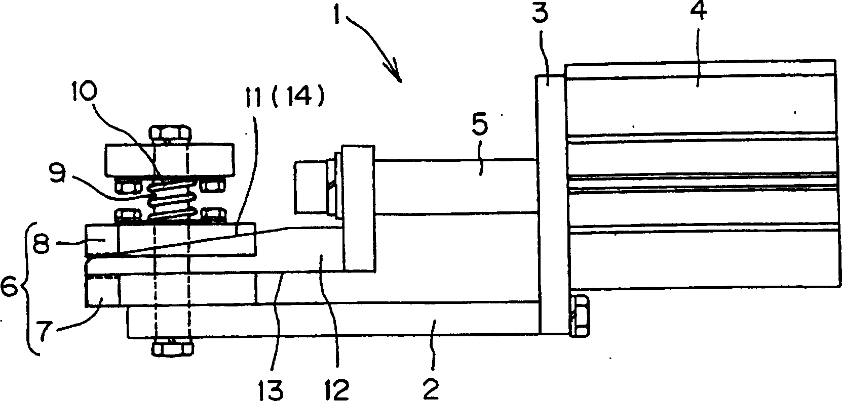
[0028] Figure 1 ~ Figure 4 It relates to the fixed electrode tip removal device of the first embodiment of the present invention. figure 1 is the top view of the main part, figure 2 is its front view, image 3 It is an action explanatory diagram, Figure 4 It is an explanatory diagram for setting the electrode tip on the electrode tip removal device.

[0029] In the figure, 1 represents the overall view of the fixed electrode head removal device, on which a drive device 4 is installed on the base 2 of the fixed electrode head removal device 1 through a bracket 3 . As the driving means 4, a known driving mechanism such as reciprocating movement of the cylinder pressurizing rod 5, reciprocating movement of the pressurizing rod 5 by means of a motor extending from a motor and including a screw and a nut can be suitably used.

[0030] 6 is a detachment claw member, which is composed of a fixed detachment claw member 7 fixed on the base plate 2 and a movable detachment claw m...

no. 2 example

[0040] Figure 5~ Figure 7 Referring to the fixed electrode tip removal device according to the second embodiment of the present invention, Fig. 5 is a front view of main parts, Figure 6 is its left side view, Figure 7 It is an explanatory diagram for setting the electrode tip on the electrode tip removal device.

[0041] In this second embodiment, the dismounting claw members are arranged in upper and lower layers, and the upper and lower layers of wedges are used to make these dismounting claw members move simultaneously, which is different from the above-mentioned first embodiment, and other structures are essentially the same Since the examples are the same, the same components are given the same reference numerals and their descriptions are omitted.

[0042] That is to say, the dismounting claw member 6 is arranged in upper and lower layers, the dismounting claw member 6 of the upper layer makes the fixed dismounting claw member 7 be located at the upper part, the mov...

no. 3 example

[0047] Figure 8 ~ Figure 10 Relating to the fixed electrode tip removal device of the third embodiment of the present invention, Figure 8 is the main part front view, Figure 9 and Figure 10 is an explanatory diagram of its operation.


PUM


Abstract

There is provided a fixed type electrode tip removal device capable of reliably removing an electrode tip and realizing full automation of the removal device. The fixed type electrode tip removal device for removing an electrode tip from the shank is made up of a take-out claw member provided with a substantially semi-circular claw for being brought into contact with an end face of the shank and an end face of the electrode tip in a gap between a large diameter portion of the shank and the electrode tip, the take-out claw member being disposed at the tip end of the removal device, wherein the end face of the electrode tip is pressurized by the claw in the direction of an axis of the electrode tip to remove the electrode tip from the shank, the take-out claw member being made up of a fixed take-out claw member fixed to a base plate and a movable take-out claw member movable relative to the base plate, a driving unit fixed to the base plate, a wedge connected to a pressure application rod from the driving unit, the wedge having a flat face at one side and a tapered inclined face at the other side, and an inclined face formed on the movable take-out claw member contacting the inclined face of the wedge.

Description

[0001] The present invention relates to a device for detaching from a shank a welding electrode tip taper-fitted on the shank. Background technique [0002] In the past, the device for dismounting the welding electrode tip taper-fitted on the shank from the shank, at the gap between the large diameter portion of the shank and the electrode tip, the end surface of the shank and the end surface of the electrode tip are respectively overlapped. A detachment claw member with a substantially semicircular claw is provided on the front end side of the detachment device, and the electrode tip is detached from the handle by pressing the end face of the electrode tip with the claw in the axial direction of the electrode tip. (For example, see Patent Document 1). [0003] Patent Document 1: [0004] Japanese Patent Laid-Open No. 2001-347380 [0005] However, what is disclosed in the above-mentioned background technology is a movable detachment device, which makes the electrode tip deta...

Claims


Application Information

Patent Timeline
Patent Type & Authority Applications(China)
IPC IPC(8): B23K11/30
CPCB23K11/3072B23K11/30B23K11/36B23K37/00B23P19/04
Inventor 和泉武宏菅野考司早藤健司
Owner OHARA
Learn More