Method for setting offset set value of warp take-up device and warp take-up device

A technology of coiling device and setting value, used in warping machines, transportation and packaging, other manufacturing equipment/tools, etc., can solve the problems of disordered coiling posture, unavailability, cracking of weaving shafts, etc.

Inactive Publication Date: 2005-02-09
TSUDAKOMA KOGYO KK
View PDF0 Cites 9 Cited by
  • Summary
  • Abstract
  • Description
  • Claims
  • Application Information

AI Technical Summary

Problems solved by technology

For this setting operation, it is necessary to wind a warp sheet of a certain length. During the setting operation, the warp sheet is wound under a state where the winding tension is different from the required value. As a result, due to the winding tension Insufficient enough to cause the disorder of the winding posture, that is, the occurrence of the so-called weaving beam crack, or the failure to make a good quality warp beam
The low quality of this warp beam appears in the following forms, for example, in the above-mentioned warp preparation process, the warp quality abnormalities such as yarn breakage due to the mutual entanglement of adjacent warp yarns, and warp yarn quality abnormalities in the weaving process. Phenomenon in which the production efficiency of the loom decreases due to weft breakage due to poor shedding and repeated warp breakage
In this way, the warp yarn piece wound up during the setting operation cannot be used and discarded due to the obstacles caused in the operation of the above-mentioned loom, so there is also a problem from the viewpoint of effectively using the warp yarn.

Method used


Image

  • Method for setting offset set value of warp take-up device and warp take-up device
  • Method for setting offset set value of warp take-up device and warp take-up device
  • Method for setting offset set value of warp take-up device and warp take-up device

Examples


Embodiment Construction

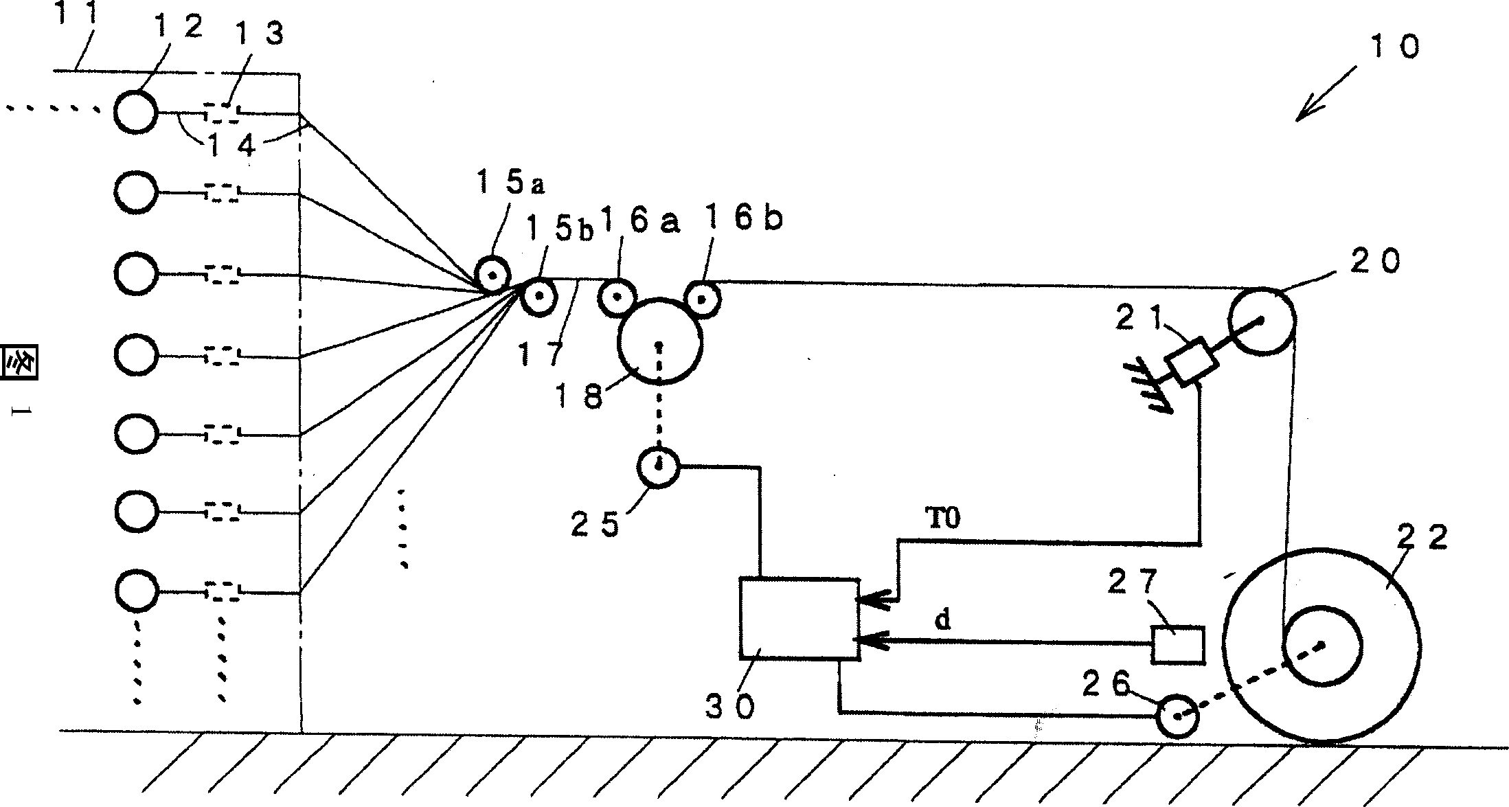
[0022] Embodiments of the present invention will be described below with reference to the drawings. Fig. 1 shows the whole of a warp winding device 10 installed in a factory. Generally speaking, the warp yarn winding device 10 includes: a warp creel 11 that is loaded with many yarn supply bodies 12; and a winding shaft 22 for winding the warp yarn sheet 17.

[0023] On the beam creel 11, a plurality of yarn supply bodies 12 are arranged side by side in the up-down, left-right, and front-back directions, and a tensioner 13 is provided on each yarn supply body. Also, between the creel 11 and the rotatable tension roller 18 arranged in front of it, a pair of guide rollers 15a, 15b that overlap each other in the vertical direction and are separated are arranged. Adjacent guide rollers 16a, 16b. The warp yarn 14 drawn out from each yarn supply body 12 through the tensioner 13 is formed into a warp yarn sheet 17 by making a pair of guide rollers 15a, 15b combined into one, and is...


PUM


Abstract

The invention provides a warp winder in which the action force of a take-up roll is imparted to a warp sheet drawn out from a creel to wind up the warp sheet on a winding beam with a desired winding tension and in which the imparted torque of the take-up roll can efficiently and accurately set to give the desired winding tension. This method for setting a bias-setting value to a warp winder is characterized by performing the first process for temporarily setting a prescribed value as the bias-setting value and simultaneously rotating the winding beam to detect the total tension of the warps with a tension sensor, and the second process for setting a value obtained by subtracting the total tension of the warps from the sum of a set winding tension value and the prescribed value, as the bias selling value for the winding operation.

Description

technical field [0001] The present invention relates to a warp sheet drawn out from a creel by applying the force of a tension roller to wind it up on a take-up shaft with a required take-up tension in warpers and the like in the fiber industry. The technology of the warp yarn winding device relates more specifically to the technology of setting the force of the tension roller acting on the warp yarn sheet. Background technique [0002] In warp preparation machines such as warpers and sizing machines, a plurality of yarns are drawn out from a plurality of yarn suppliers installed on the creel through a tensioner, and after being combined into a sheet, they are combined with a sheet. The peripheral surfaces of the tight rolls are in contact, and then wound up on the take-up shaft, thus making the structure of the warp beam. For this warp winding device, for example, Japanese Patent No. 2696550 (page 1~page 2, Figure 4 ) shown. More specifical...

Claims


Application Information

Patent Timeline
Patent Type & Authority Applications(China)
IPC IPC(8): B65H54/02B65H59/38D02H7/00D02H13/00D02H13/08D02H13/14D02H13/22D02H13/26
CPCB65H54/02B65H59/38D01H13/10D02H7/00D02H13/08D02H13/14D02H13/26
Inventor 野村拓右
Owner TSUDAKOMA KOGYO KK
Why Eureka
Try Eureka