Automatic directional valve device

An automatic reversing and valve device technology, applied in the direction of valve devices, valve operation/release devices, water supply devices, etc., can solve the problems of many components and increased manufacturing difficulty, so as to reduce the number of components, reduce the difficulty of assembly, The effect of improving the response speed

Inactive Publication Date: 2005-02-09
孙和铉
View PDF1 Cites 10 Cited by
  • Summary
  • Abstract
  • Description
  • Claims
  • Application Information

AI Technical Summary

Problems solved by technology

[0005] However, in the above-mentioned automatic reversing valve device, in order to transmit the fluid pressure sent to the output pipeline to the pressure chamber of the reversing body, a fluid pressure transmission pipeline must be connected between the pressure chamber of the reversing body and the output pipeline.
[0006] In terms of structural characteristics, the above-mentioned fluid pressure transmission pipeline can only be placed outside the automatic reversing valve device.
Because the fluid pressure transmission pipeline is exposed outside, it is necessary to prevent freezing when used in cold areas, so it is bound to bring the disadvantages that the entire automatic reversing valve device must be covered with a protective cover for protection.
[0007] Moreover, the reversing body, connecting rod mechanism, control module mechanism, reset mechanism and valve chamber all need to be manufactured independently. There are too many components, which makes the production more difficult, and it takes a lot of effort to ensure its performance and quality during assembly. Product Confidentiality

Method used


Image

  • Automatic directional valve device
  • Automatic directional valve device
  • Automatic directional valve device

Examples


Embodiment Construction

[0034] The following is a detailed description of the automatic reversing valve device according to the drawings in the appendix.

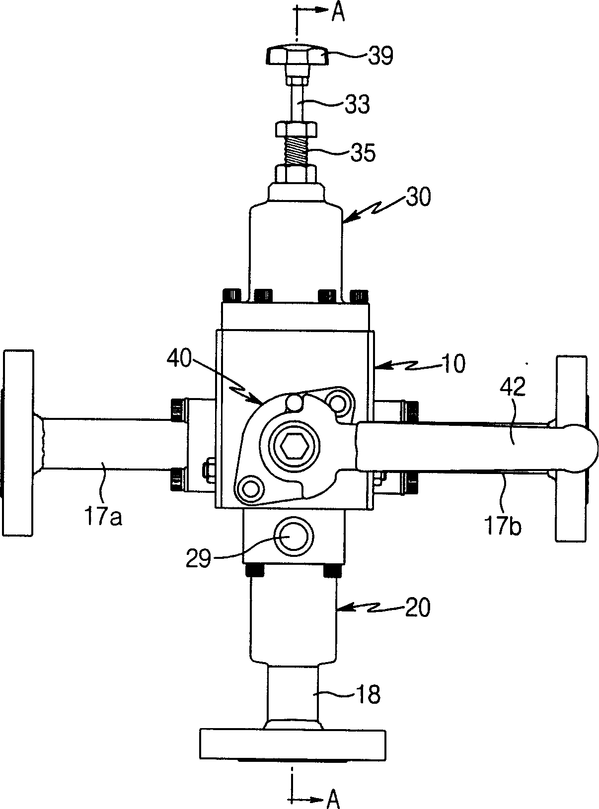
[0035] Figure 1 to Figure 6 It is the overall / partial schematic diagram of the LPG automatic reversing valve device in the present invention.

[0036] As shown in the figure, two LPG supply pipes 17a, 17b and an output pipe 18 are provided on the reversing body 10, and the LPG is output to the vertical steam pipe through the supply pipe 17a, 17b, and the C circuit through the output pipe 18. equipment. The bottom, top and front of the reversing body 10 are respectively fixed with a link mechanism 20 , a control die mechanism 30 and a reset mechanism 40 .

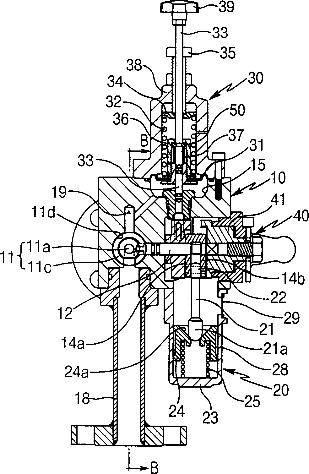
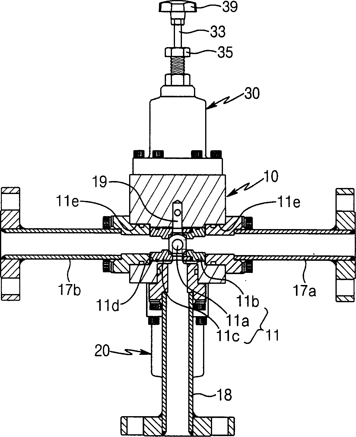
[0037] Such as figure 2 As shown, one side of the reversing body 10 forms a valve chamber 11d that communicates with the supply pipes at both ends of the reversing body 10. There are two concentric holes 11e that communicate with the supply pipes 17a and 17b at both ends of the valve chambe...


PUM


Abstract

The invention relates to an automatic change valve, which aims at integrating a three way chamber with the reversing body into a whole toward less components and easy assembly. Moreover, a pressure chamber and a valve chamber of the reversing body are communicated via a fluid transmission passage for anti-freezing and quick response when used in cold regions. The invention is characterized in that: an output pipe (18) is vertically arranged at two supply pipes (17 a, 17b); a valve reversing body (10) is arranged between the supply pipes (17a, 17b) and the output pipe (18); a linkage (20) fixed at the valve reversing body (10) can determine whether the reversing is executed based on the position of a piston (24); a control diaphragm (30) arranged at the valve reversing body (10) for locking or unlocking a reversing tray (13); a resetting element (40) fixed at the valve reversing body (10) for manually rotating the valve shaft (12) and the reversing components (14) on the valve shaft (12). The valve chamber (11d) for mounting three-way valve (11) is positioned at the lower part of the valve reversing body (10); two holes (11e) are respectively arranged at ends of the valve chamber for connecting with the supply pipe; the fluid transmission passage (19) connects between a pressure chamber with the control diaphragm (30) and the valve chamber (11d). The control diaphragm (30) comprises: a control diaphragm (31) manually operated with a push for reversing; a diaphragm cover (36) covering the control diaphragm (31) and a third spring (37); a valve rod (33) outwards extending to the direction of the control diaphragm (31) and the reversing disk (13) inside the valve reversing body, then penetrating the diaphragm cover (36), a second cylinder (38) and a bolt (35); as well as the third spring (37) inside the diaphragm cover (36) to enable the valve rod (33) under the constant thrust away from the reversing disk (13).

Description

technical field [0001] The present invention is an automatic reversing valve device (auto-change valve) that automatically switches to the fluid supply pipeline on the other side when the fluid margin on one side of the two fluid supply pipelines drops below a specified pressure, so that the fluid can be continuously supplied to the use side. apparatus). Background technique [0002] In order to continuously supply liquefied gas to the vertical steam pipe (vapor riser) of the liquefied gas (LPG) engine or the gas stove, usually connect two liquefied gas tanks (LPG bomb) (including spare tanks), and install automatic reversing in the gas supply circuit valve. When the balance of the normally used liquefied gas tank drops below the specified pressure, it will automatically switch to the spare liquefied gas tank as its pressure drops to the bottom. [0003] The automatic reversing valve device related to the above-mentioned technology has been published on the Japanese Laid-O...

Claims


Application Information

Patent Timeline
IPC IPC(8): F16K11/00F16K11/08F16K31/00
CPCE03B7/12F16K11/00F16K31/60
Inventor 孙和铉
Owner 孙和铉
Why Eureka
Try Eureka