Pattern inspection method and apparatus, and pattern alignment method

An inspection method and pattern technology, applied in functional inspection, image analysis, image data processing, etc., can solve problems such as pattern defects and loss of defective patterns

Inactive Publication Date: 2005-02-09
NIPPON AVIONICS CO LTD
View PDF8 Cites 28 Cited by
  • Summary
  • Abstract
  • Description
  • Claims
  • Application Information

AI Technical Summary

Problems solved by technology

Originally defect-free patterns to be measured may be detected as defects, or defective patterns may be lost

Method used


Image

  • Pattern inspection method and apparatus, and pattern alignment method
  • Pattern inspection method and apparatus, and pattern alignment method
  • Pattern inspection method and apparatus, and pattern alignment method

Examples


no. 1 example

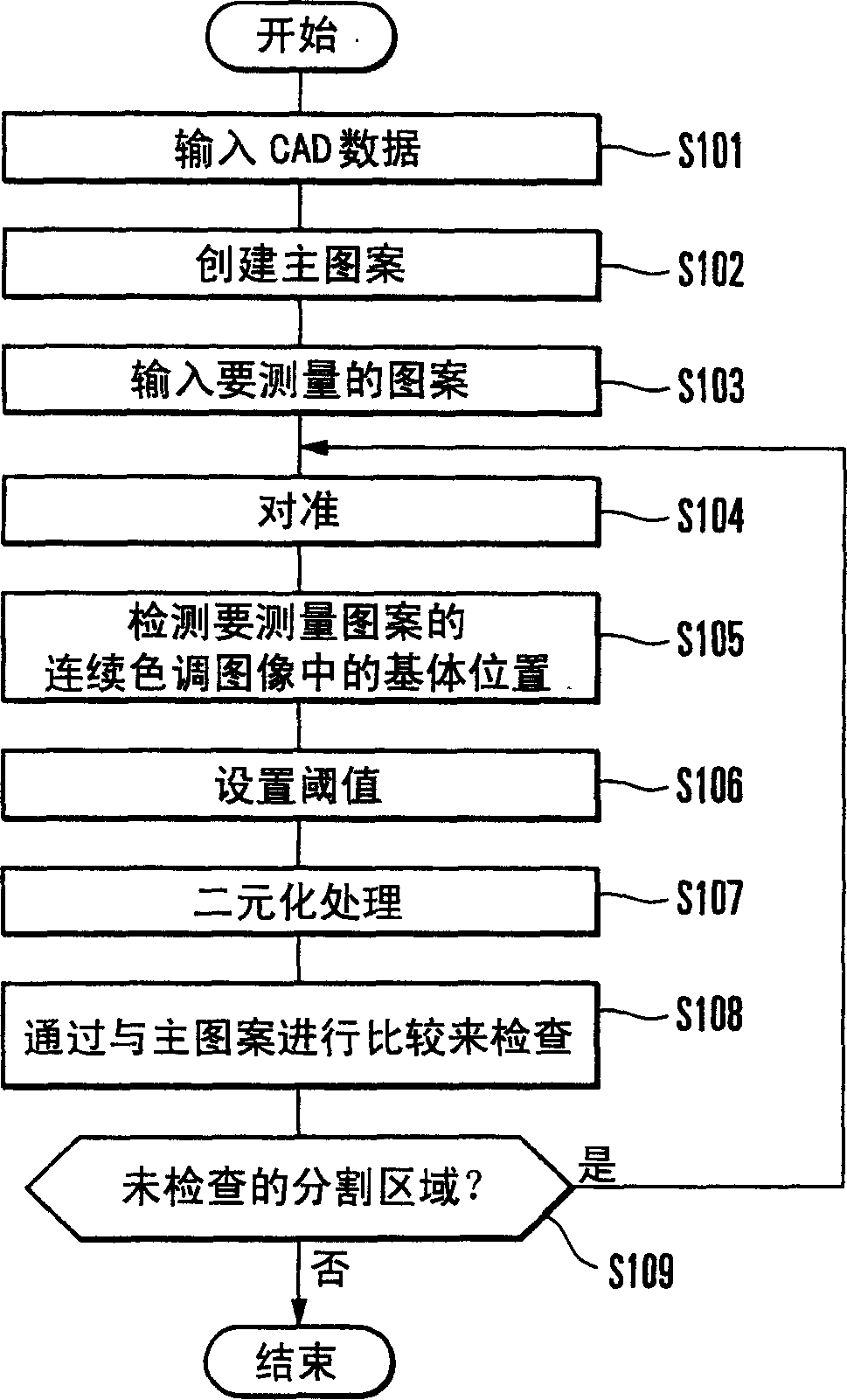
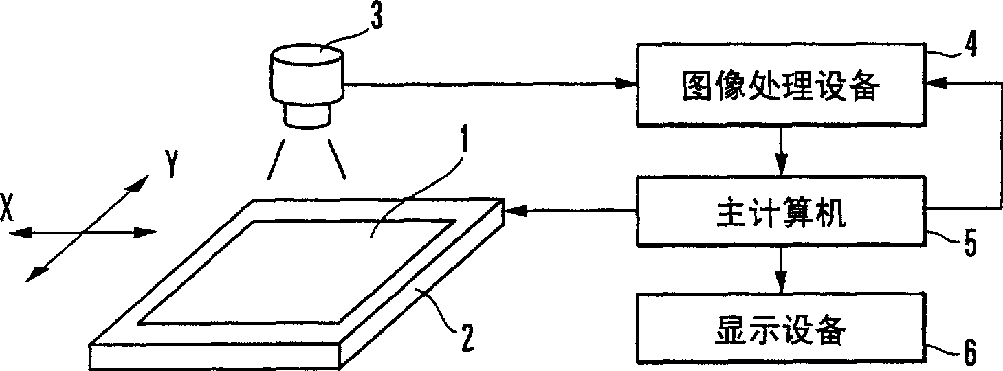
[0045] A first embodiment of the present invention will be explained in detail below with reference to the drawings. figure 1 A pattern detection method according to a first embodiment of the present invention is shown. figure 2 A pattern inspection device used in this inspection method is shown. exist figure 2 In, reference numeral 1 denotes an inspection workpiece such as a printed circuit board; reference numeral 2 denotes an X-Y table supporting the inspection workpiece 1; reference numeral 3 denotes a line sensor camera for sensing the inspection workpiece 1; reference numeral 4 denotes a main The pattern is compared with the pattern to be measured perceived by the camera 3, and an image processing device that checks the pattern to be measured; reference numeral 5 denotes a host computer that controls the entire device; and reference numeral 6 denotes a display device that displays the inspection result.

[0046] The image processing apparatus 4 includes: alignment m...

no. 2 example

[0107] In the first embodiment, the continuous tone image data of the pattern to be measured is binarized at the threshold SH1 at which the difference from the density value of the base is always kept constant. However, binarization with a single threshold SH1 may miss pattern defects even if no density change has occurred.

[0108] like Figure 10 As shown, the density value of the defect or disconnected part is higher than the density value of the matrix and close to the density value of the conductor. On the contrary, the density value of the protruding portion or the short-circuit portion is smaller than that of the conductor and close to that of the matrix. For this reason, binarization with a single binarization threshold SH1 converts a defect such as a chip or a disconnection into "1", and converts a defect such as a protrusion or a short into "0". Even for Figure 10 Inspections performed on the binarized results are also unable to detect such defects.

[0109] As ...

no. 3 example

[0118] In the first and second embodiments, the threshold is set so that the difference from the density value of the matrix is ​​always constant. It is also possible to set the threshold so that the ratio of the difference between the threshold and the density value of the matrix to the difference between the density values ​​of the conductor and the matrix is ​​always constant.

[0119] When the threshold value setting method of the third embodiment is applied to the first embodiment, the host computer detects the positions of the substrate and the conductor in the continuous tone image of the pattern to be measured ( figure 1 in step S105). Similar to the base position, the conductor position can also be obtained from the master pattern aligned in step S104. Such as Figure 13A As shown, the host computer 5 sets the threshold SH1 so that the ratio DF1 / DF4 of the difference DF1 between the threshold SH1 and the density value of the matrix to the difference DF4 between the...


PUM


Abstract

In a pattern inspection method, a master pattern serving as a reference and the continuous tone image of a pattern to be measured that is sensed by a camera are aligned. At least the position of a base in the continuous tone image of the pattern to be measured is detected on the basis of the master pattern. At least one threshold is set on the basis of the difference from at least the density value of the base. The continuous tone image of the pattern to be measured is binarized on the basis of the set threshold. The pattern to be measured is inspected by comparing the binarized pattern to be measured and the master pattern. A pattern inspection apparatus and alignment method are also disclosed.

Description

technical field [0001] The present invention relates to a pattern inspection method and apparatus for inspecting a pattern formed on a printed circuit substrate, a film carrier, etc., and an alignment method for aligning a master pattern and a pattern to be measured. Background technique [0002] In general, PGA (Pin Grid Array) is known as a packaging technology that meets the requirements of multi-pin ICs and LSIs. The PGA employs a ceramic substrate as a base for a package for an attached chip, and forms wiring to guide a wire extraction position. The formation of the ceramic substrate used a so-called printed circuit board prepared by kneading alumina powder into a substrate with a liquid binder. A colloid comprising a refractory metal is screen printed onto the printed circuit substrate. Baking the substrate to sinter the printed circuit substrate and metallize the colloid is called co-sintering. [0003] Another packaging technology is TAB (Tape Automated Bonding). ...

Claims


Application Information

Patent Timeline
Patent Type & Authority Applications(China)
IPC IPC(8): H01L23/12G01B11/30G01R31/00G06F17/50G06K9/00G06Q99/00G06T7/00H01L21/66
CPCG06T7/0026G06T7/001G06T7/32G06F17/00H01L22/00G06F11/26H01L23/12
Inventor 服部新一井田彻松野修三
Owner NIPPON AVIONICS CO LTD
Why Eureka
Try Eureka