Check patentability & draft patents in minutes with Patsnap Eureka AI!

Lithographic apparatus, device manufacturing method, and device manufactured thereby

A lithographic projection and beam technology, which is used in semiconductor/solid-state device manufacturing, photolithography process exposure devices, microlithography exposure equipment, etc., can solve problems such as the inability to achieve the optimal accuracy of projected images and the inaccuracy of positioning and patterning devices.

Inactive Publication Date: 2005-02-09
ASML NETHERLANDS BV
View PDF9 Cites 1 Cited by
  • Summary
  • Abstract
  • Description
  • Claims
  • Application Information

AI Technical Summary

Problems solved by technology

On the other hand, it is foreseeable that optimal accuracy of the projected image cannot be achieved when mechanical docking systems are used
[0021] In addition, it was found that when the patterning device was transferred from the reticle carrier to the reticle stage, there was an inaccuracy in positioning the patterning device relative to the reticle stage

Method used


Image

  • Lithographic apparatus, device manufacturing method, and device manufactured thereby
  • Lithographic apparatus, device manufacturing method, and device manufactured thereby
  • Lithographic apparatus, device manufacturing method, and device manufactured thereby

Examples


Embodiment Construction

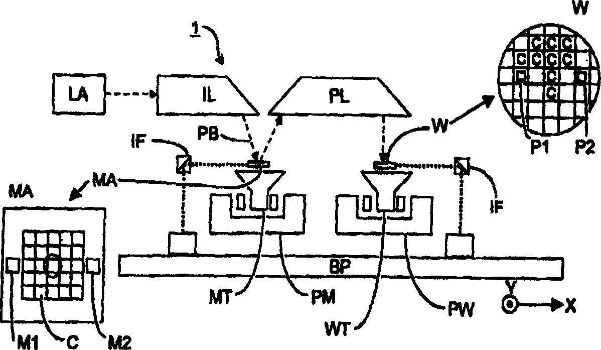
[0161] figure 1 A lithographic projection apparatus 1 according to a specific embodiment of the present invention is schematically shown. The unit includes:

[0162] - a radiation system Ex, IL for providing a radiation projection beam PB (eg EUV radiation), in this particular case also comprising a radiation source LA;

[0163] - a first target table (mask table) MT provided with a mask holder for holding a mask MA (e.g. a reticle) and with first positioning means for precisely positioning the mask relative to the object PL PM connection;

[0164] - a second target table (substrate table) WT provided with a substrate holder for holding a substrate W (e.g. a resist-coated silicon wafer) and with second positioning means for precise positioning of the substrate relative to the object PL PW connection; and

[0165] - A projection system ("lens") PL (eg a mirror arrangement) for imaging a radiation portion of the mask MA onto a target portion C of the substrate W (eg comprisi...


PUM


Abstract

The invention pertains to a lithographic apparatus comprising a radiation system for providing a projection beam of radiation, a patterning means (1) serving to pattern the projection beam according to a desired pattern, thus creating a patterned beam, a support structure for supporting the patterning means (1), the support structure comprising a reticle stage and a projection system for projecting the patterned beam onto a target portion of a substrate. According to the first aspect of the invention, the lithographic apparatus further comprises a docking system for positioning the patterning means (1) relative to the reticle stage. The lithographic projection apparatus has an operational cycle comprising a projection phase, in which the projection system projects the patterned beam onto a target portion of the substrate, and in which the reticle stage carries the patterning means (1) and an exchange phase in which the patterning means (1) is exchanged, and in which the docking system positions the patterning means (1) relative to the reticle stage. The lithographic apparatus according to the first aspect of the invention is characterized in that the docking system is spaced from the patterning means (1) during the projection phase. This way, a higher accuracy of the projected image is obtained.

Description

technical field [0001] The invention relates to a photolithographic projection device, [0002] include: [0003] - a radiation system for providing a radiation projection beam; [0004] - a support structure for supporting a patterning device for patterning the projected beam according to a desired pattern; [0005] - a substrate table for holding the substrate; [0006] - A projection system for projecting a patterned light beam onto a target portion of a substrate. Background technique [0007] The term "patterning device" as used herein should be broadly interpreted as a device capable of imparting a patterned cross-section to an incident radiation beam, wherein said pattern corresponds to a pattern to be formed on a target portion of a substrate; the term "patterning device" is also used herein light valve". Generally, the pattern corresponds to a specific functional layer of a device, such as an integrated circuit or other device, formed in the target portion (as ...

Claims


Application Information

Patent Timeline
Patent Type & Authority Applications(China)
IPC IPC(8): G03F7/20H01L21/00H01L21/027
CPCG03F7/70741G03F7/709G03F7/70716G03F7/70825G03F7/707G03F7/70783
Inventor B·L·W·M·范德文G·-J·希伦斯R·G·M·兰斯伯根M·H·A·里德斯E·R·鲁普斯特拉
Owner ASML NETHERLANDS BV
Features
  • R&D
  • Intellectual Property
  • Life Sciences
  • Materials
  • Tech Scout
  • Unparalleled Data Quality
  • Higher Quality Content
  • 60% Fewer Hallucinations
Learn More