Method for positioning first-on rotor for alternating current permanent-magnet synchronous motor control system

A permanent magnet synchronous motor and motor rotor technology, applied in control systems, electronic commutation motor control, electrical components, etc., can solve problems such as long positioning time, wrong positioning, and complex systems

Active Publication Date: 2005-02-16
桂林星辰科技股份有限公司
View PDF1 Cites 19 Cited by
  • Summary
  • Abstract
  • Description
  • Claims
  • Application Information

AI Technical Summary

Problems solved by technology

For example, Chinese patent 96106988 "Method and device for detecting the initial position of the motor rotor in the AC servo system", this invention can realize the measurement of the initial position of the motor rotor while controlling the motor rotor to rotate the encoder line, and overcomes the need for development in the prior art. Disadvantages of ring rotating once to find the initial zero position
However, this invention uses a trial and error method to find the zero position of the rotor point by point by changing the applied current from small to large and measuring the running trend of the motor. The positioning time is long, the calculation is complicated, and the system is complex. Mispositioning will occur

Method used


Image

  • Method for positioning first-on rotor for alternating current permanent-magnet synchronous motor control system

Examples


Embodiment Construction

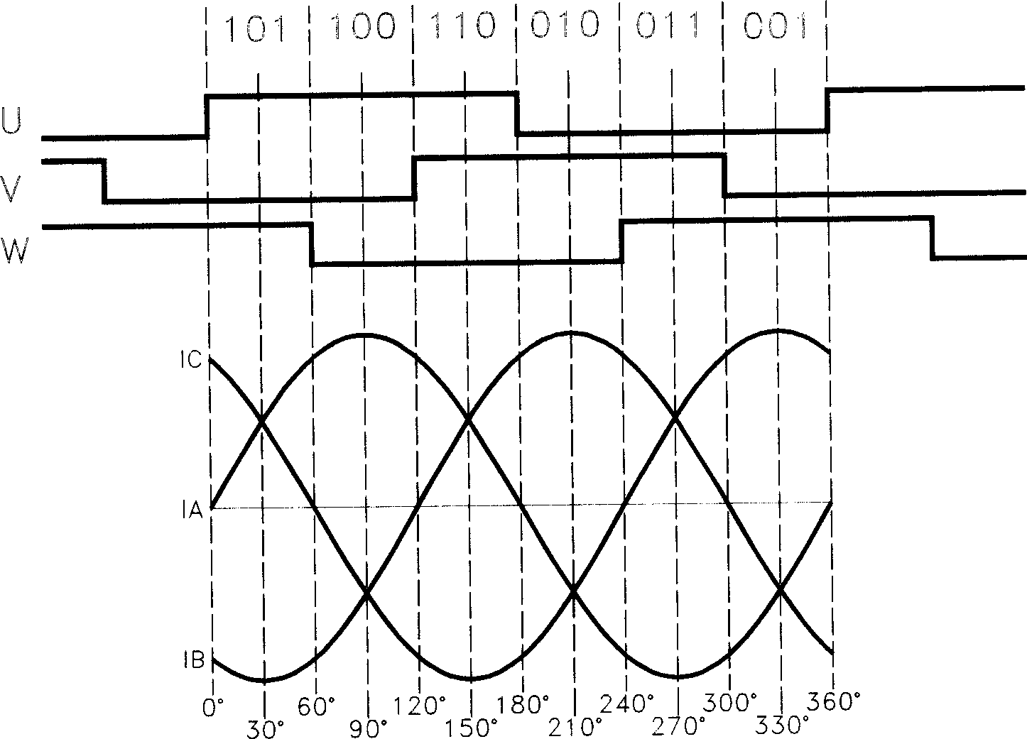
[0010] Install an ordinary incremental encoder on the rotor of the motor, and use the number of A and B pulses it outputs to represent the change of the rotor position. At the same time, when the motor is manufactured, the induction Hall element of the rotor magnetic pole position is pre-installed and equipped with a common incremental encoder, or a special incremental encoder with U, V, W signals is installed. Such as figure 1 As shown, the U, V, and W state signals sent by the Hall element or the encoder have a total of six level states, 101, 100, 110, 010, 011, and 001, which represent the electrical angle position of the motor rotor. Six equidistant interval, each interval is 360÷6=60° electrical angle. At the initial power-on moment, the U, V, and W signal states sent by the incremental encoder determine the interval where the initial position of the rotor magnetic field vector of the motor is located. The midpoint of this interval is taken as the rotor magnetic field ve...


PUM


Abstract

General encoder and Hall component or increment type encoder capable of transmitting U, V, W signals are installed on rotor. U, V, W signals divide electrical angle of rotor position into six intervals in 60 degrees each. At strating up time of power on, magnetic vector intervals of rotor are determined through U, V, W signal states. The middle point of the interval is as position of magnetic vector of rotor. Controller outputs electrical current to three-phase winding of stator. Maximum phase error of current is only 30 degrees. When rotating rotor steps across interval, first change of U, V, W signal states occurs. Thus, accurate positioning for rotor is carried out, and normal operation begins. System checks position of rotor in every 60 degree in order to avoid positioning error in operation.

Description

(1) Technical field [0001] The invention relates to a rotor positioning method of an AC permanent magnet synchronous motor control system, in particular to a rotor positioning method when the AC permanent magnet synchronous motor control system is powered on for the first time. (2) Technical background [0002] When performing servo control on an AC permanent magnet synchronous motor, the controller controls the vector direction of the stator three-phase current synthetic magnetic field. In order to effectively control the stator magnetic field vector, accurate measurement of the rotor position is required. Usually an economical and effective method is to install an incremental encoder on the motor rotor, and use the number of encoder output pulses to represent the change of the rotor position. But in this method, the control computer of the controller needs to obtain the initial position of the rotor first, and then determine the direction of rotation and the angle of rota...

Claims


Application Information

Patent Timeline
Patent Type & Authority Applications(China)
IPC IPC(8): H02P6/00H02P6/20
Inventor 吕虹
Owner 桂林星辰科技股份有限公司
Why Eureka
Try Eureka