
Ping-pong amplifier with auto-zeroing and chopping

A technology of automatic zero adjustment and differential amplifier, applied in the field of ping-pong amplifiers, which can solve problems such as limitations

Inactive Publication Date: 2005-02-16
ANALOG DEVICES INC
View PDF0 Cites 5 Cited by
  • Summary
  • Abstract
  • Description
  • Claims
  • Application Information

AI Technical Summary

Problems solved by technology

This energy limits the available bandwidth and often requires filtering

Method used


Image

  • Ping-pong amplifier with auto-zeroing and chopping
  • Ping-pong amplifier with auto-zeroing and chopping
  • Ping-pong amplifier with auto-zeroing and chopping

Examples


Embodiment Construction

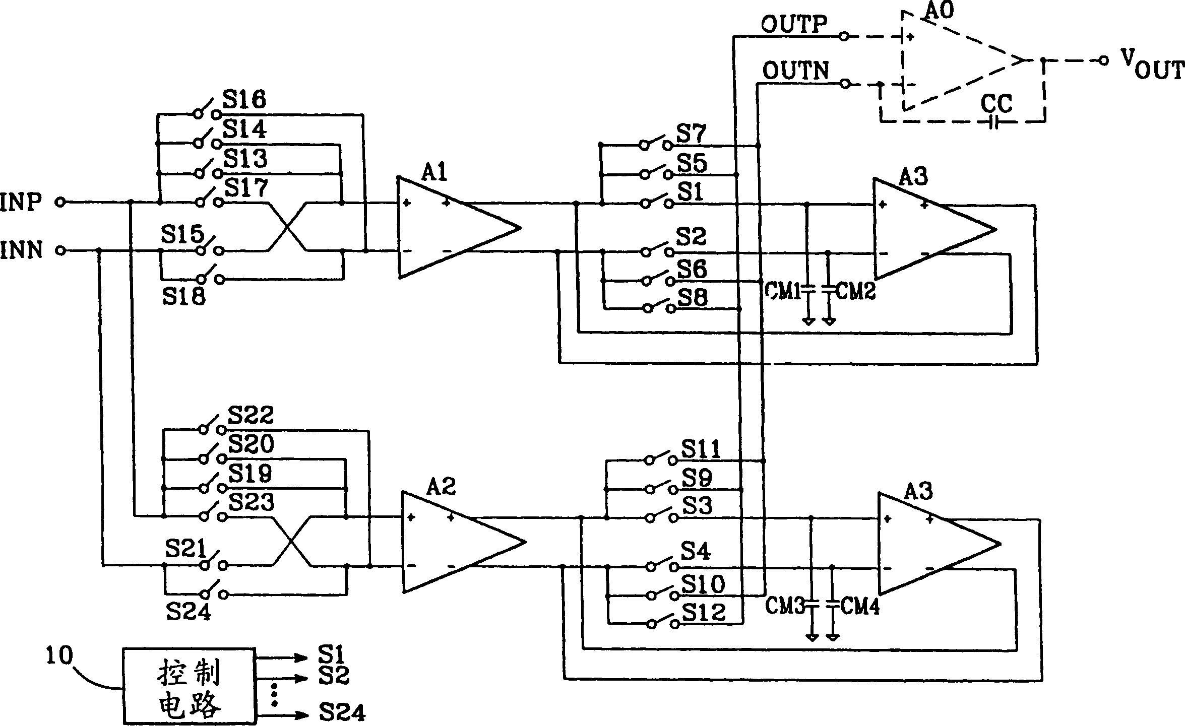
[0018] Figure 2a Shown is a schematic diagram of a ping-pong amplifier illustrating the principles of the invention. The ping-pong amplifier receives a differential input signal consisting of positive and negative lines INP and INN. A pair of fully differential gain amplifiers A1 and A2 each receive a differential input signal through a switch array discussed below. The differential output terminal of A1 is connected to a fully differential null amplifier A3 through a pair of switches S1 and S2 and the output terminal of A2 is connected to a fully differential null amplifier A4 through a pair of switches S3 and S4. A pair of storage capacitors CM1 and CM2 are respectively connected to the non-inverting and inverting input terminals of A3 and the non-inverting and inverting output terminals of A3 are respectively connected to the inverting and non-inverting output terminals of A1. Likewise, a pair of storage capacitors CM3 and CM4 are connected to the non-inverting and inver...


PUM


Abstract

A ping-pong amplifier employs auto-zeroing and chopping to simultaneously achieve low offset voltage and low frequency noise, as well as low energy at the chopping frequency. The ping-pong amplifier includes respective nulling amplifiers (A3, A4) for each of its gain amplifiers (A1, A2), which auto-zero each gain amplifier. In addition, switches are included which allow the inputs and outputs of the active gain amplifier to be chopped. Thus, while one gain amplifier is being auto-zeroed, the other gain amplifier amplifies the input signal and its inputs and outputs are chopped. One of the described embodiments includes circuitry which reduces switching transients that might otherwise appear in the amplifier's output by ensuring that the common-mode output voltage of each gain amplifier is kept equal to a common-mode reference voltage.

Description

technical field [0001] The present invention relates to the field of ping-pong amplifiers, and more specifically, relates to techniques for reducing low-frequency noise and compensating voltage errors of said amplifiers. Background technique [0002] It is well known that the ping-pong amplifier is widely used due to its low input offset voltage. A schematic diagram of a basic ping-pong amplifier 10 is shown in FIG. 1 . Both gain amplifiers A1 and A2 have a differential input terminal and an output terminal, which receive a differential input signal composed of signals INP and INN. The ping-pong amplifier usually also includes an output amplifier A0, which can be connected to the output terminal of A1 through a pair of switches S1 and S2 or connected to the output terminal of A2 through a pair of switches S3 and S4. [0003] A pair of fully differential zero amplifiers A3 and A4 make A1 and A2 perform automatic zero adjustment respectively; the input terminals of A3 and A4...

Claims


Application Information

Patent Timeline
IPC IPC(8): H03F3/72H03F3/45H03F3/68
CPCH03F3/45941H03F3/45977
Inventor A·T·K·唐
Owner ANALOG DEVICES INC
Learn More