
Current feedback operational amplifier circuit

An operational amplifier and current feedback technology, which is applied in the direction of negative feedback circuit layout, DC-coupled DC amplifier, differential amplifier, etc., can solve the problems of large static error and low gain accuracy of current feedback operational amplifier, and overcome the large static error , high slew rate, improved accuracy and linearity

Active Publication Date: 2012-03-07
FENGHUO COMM SCI & TECH CO LTD +1
View PDF3 Cites 17 Cited by
  • Summary
  • Abstract
  • Description
  • Claims
  • Application Information

AI Technical Summary

Problems solved by technology

However, due to the characteristics of the PNP and NPN transistors in the bipolar complementary process, it is difficult to be ideally symmetrical. For example, due to the difference in the VBE of the input stage PNP and NPN transistors, the offset voltage VOS, the bias current of the inverting input terminal and the bias current of the non-inverting input terminal Cause offset voltage, etc., resulting in large static error and low gain accuracy of the current feedback operational amplifier

Method used


Image

  • Current feedback operational amplifier circuit
  • Current feedback operational amplifier circuit

Examples


Embodiment Construction

[0018] The present invention will be further described in detail below in conjunction with the accompanying drawings and embodiments.

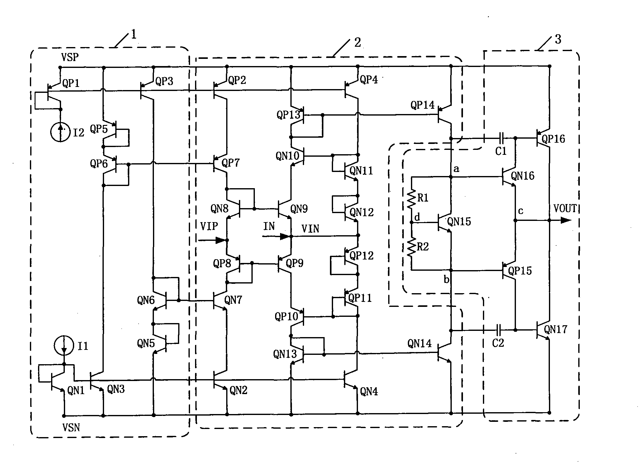
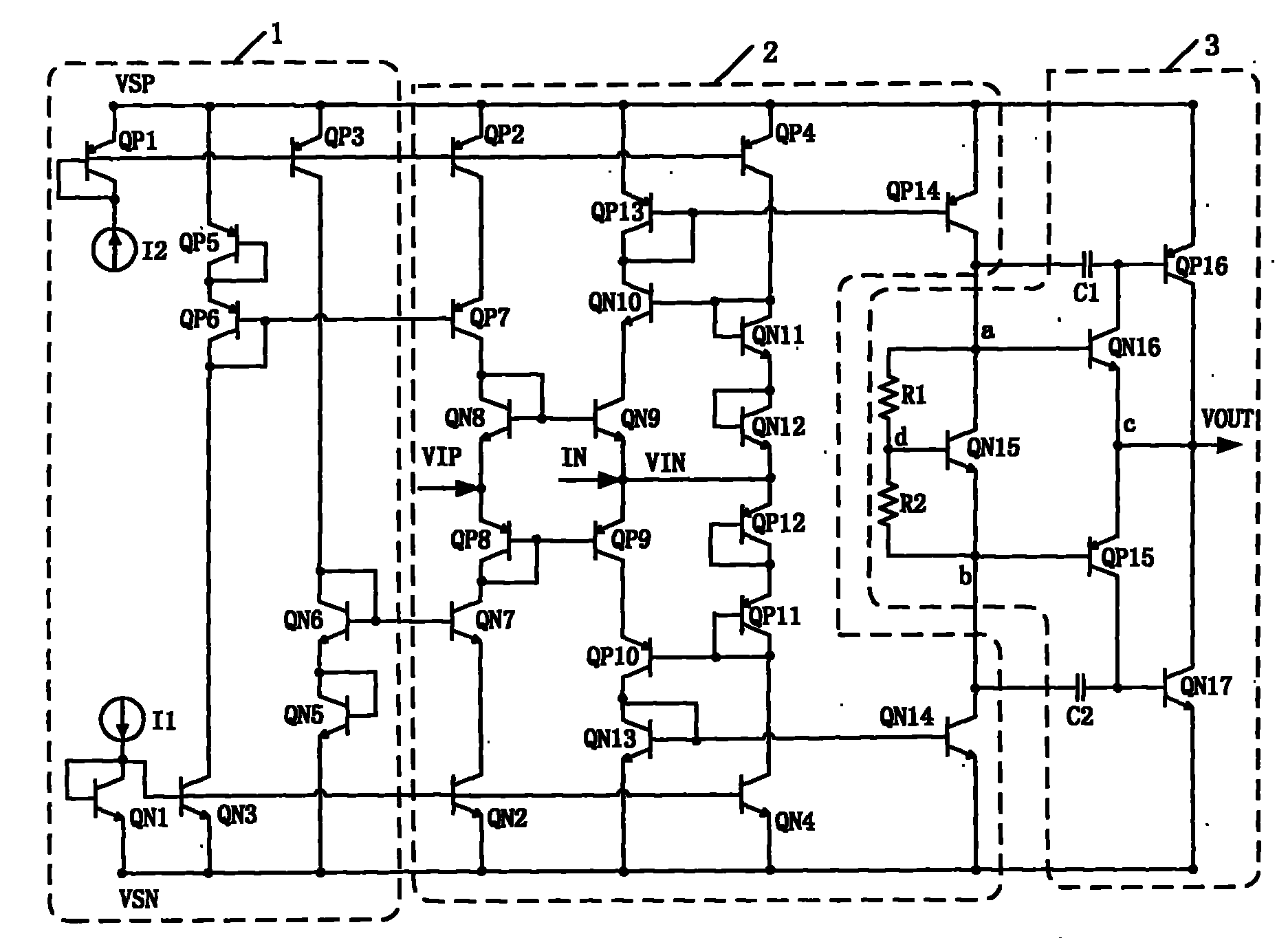
[0019] see figure 1 As shown, the current feedback operational amplifier circuit provided by the embodiment of the present invention specifically includes a power supply, a bias current supply unit 1, a first common base-common emitter current mirror, a second common base-common emitter current mirror, and a static bias circuit , sequentially connected input buffer stage and voltage conversion stage 2, drive output unit 3, the drive output unit 3 includes a bias voltage circuit and an output buffer stage, and the bias current supply unit 1 passes through the first common base-common emitter current mirror respectively , The second common base-common emitter current mirror is connected to the input buffer stage for providing bias current; the static bias circuit is respectively connected to the inverting input terminal of the input buffer stage...


PUM


Abstract

The invention discloses a current feedback operational amplifier circuit comprising a power supply, a bias current supply unit, a first common base-common emitter current mirror, a second common base-common emitter current mirror, a static bias circuit, an input buffer stage, a voltage conversion stage and a drive output unit, wherein the drive output unit comprises a bias voltage circuit and an output buffer stage; the bias current supply unit is respectively connected with the input buffer stage through the first common base-common emitter current mirror and the second common base-common emitter current mirror and used for supplying bias current; and the static bias circuit is respectively connected with the inverted input end of the input buffer stage and the voltage conversion stage and used for stabilizing a static working point of the inverted input end. The current feedback operational amplifier circuit has the advantages of lower offset voltage, stronger on-load capacity and higher conversion rate and is beneficial to improvement of the precision and the linearity of the entire operational amplifier.

Description

technical field [0001] The invention relates to a current feedback amplifier applied to a high-power drive integrated circuit, in particular to a current feedback operational amplifier circuit. Background technique [0002] The current feedback operational amplifier circuit does not have the limitation that the gain-bandwidth product is constant, so it can linearly process larger amplitude signals and respond to higher frequency signals. However, due to the characteristics of the PNP and NPN transistors in the bipolar complementary process, it is difficult to be ideally symmetrical. For example, due to the difference in the VBE of the input stage PNP and NPN transistors, the offset voltage VOS, the bias current of the inverting input terminal and the bias current of the non-inverting input terminal Cause offset voltage, etc., resulting in large static error and low gain accuracy of the current feedback operational amplifier. Contents of the invention [0003] The purpose ...

Claims


Application Information

Patent Timeline
Patent Type & Authority Applications(China)
IPC IPC(8): H03F1/34H03F3/45
Inventor 周华蒋湘任娟王丽芳吴振东
Owner FENGHUO COMM SCI & TECH CO LTD
Learn More