Braking-accelerating composite pedal board for car

A pedal and vehicle technology, which is applied in the field of vehicle brake-acceleration combination pedal, can solve the problems of personnel and property loss, and achieve the effects of strong anti-interference, shortening idling time, and not easy to malfunction

Inactive Publication Date: 2005-03-09
张淑礼
View PDF0 Cites 10 Cited by
  • Summary
  • Abstract
  • Description
  • Claims
  • Application Information

AI Technical Summary

Problems solved by technology

Traffic accidents cause heavy loss of personnel and property

Method used


Image

  • Braking-accelerating composite pedal board for car
  • Braking-accelerating composite pedal board for car
  • Braking-accelerating composite pedal board for car

Examples


Embodiment Construction

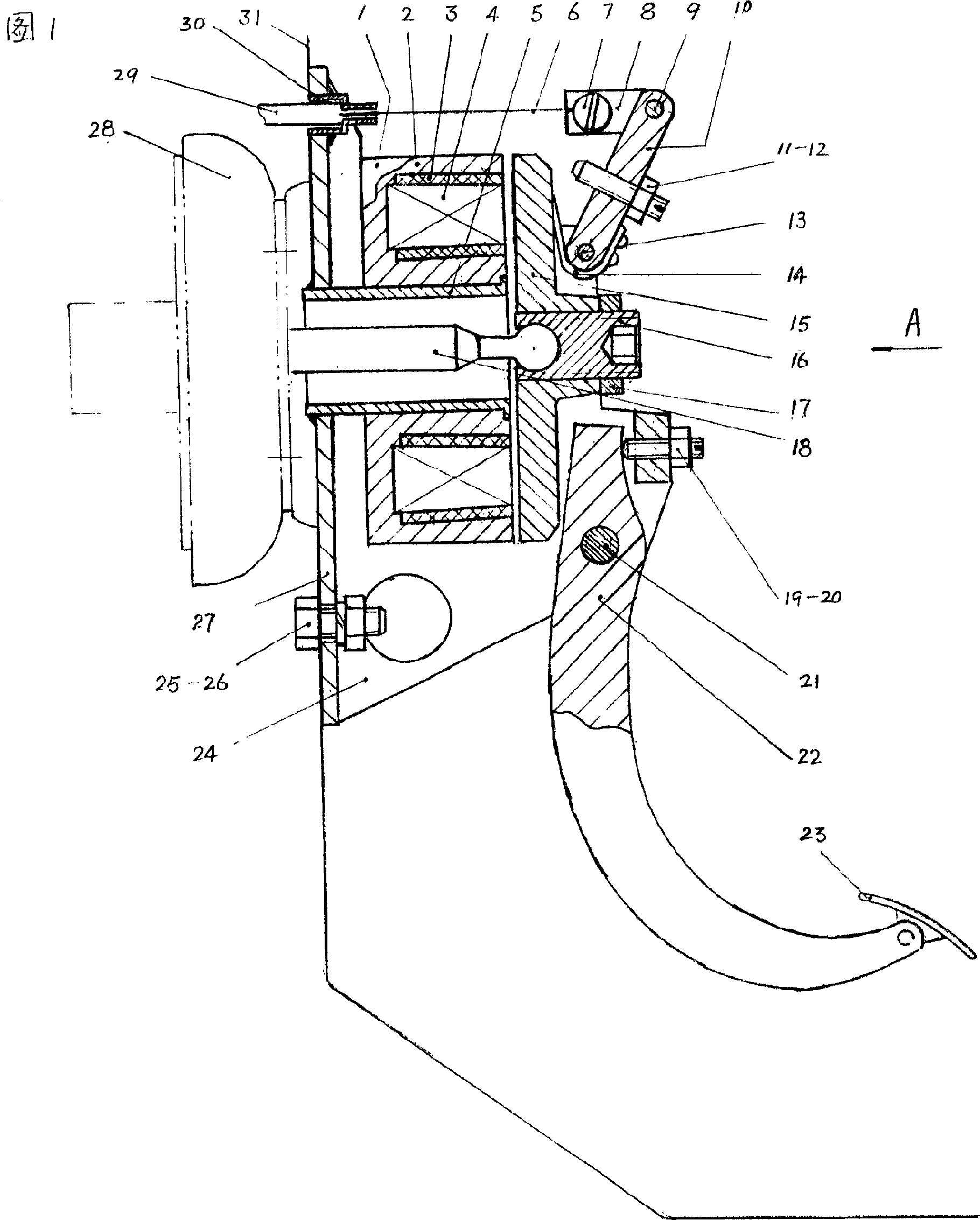
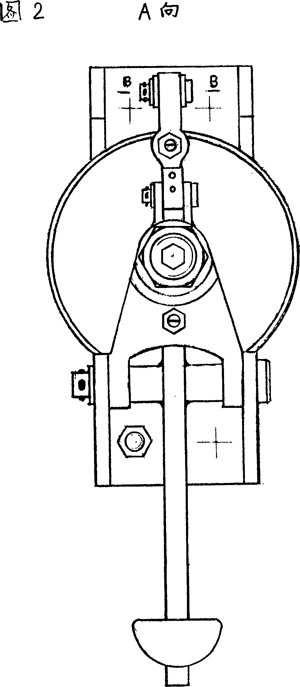
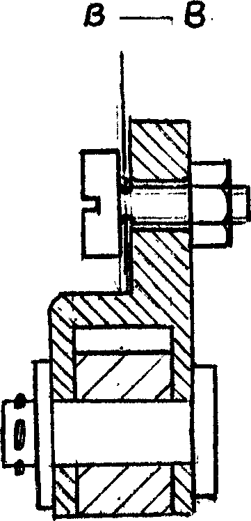
[0015] The magnetic ring body (1) is composed of a bent iron ring body (2) and a permanent magnetic ring (4), and the gap is filled with cold cast filler (3). The magnetic ring body (1) is welded with the support bottom plate (27) by the hollow casing (5) with flange. Armature plate (15) central axis direction has the through hole with internal thread, and the ball head of push rod (18) one end is contained in the spherical pit of stud (16) one end, makes ball head not deviate from with shrinking method. The other end of the push rod (18) is in contact with the piston (not shown) of the brake master cylinder, the other end of the stud (16) has a hexagonal blind hole and the nut (17) is locked, and the lower end of the armature plate (15) back is Edge tangent direction has two coaxial holes, and support side plate (24) has two holes in the same direction, and pedal arm (22) also has garden hole, and axle (21) passes all holes together. The armature plate (15) and the pedal arm...


PUM


Abstract

A combined brake-acceleration pedal for car features that the stroke of said pedal is divided into braking segment, short isolating segment and accelerating segment. The magnetic attraction of fixed magnetic ring to armature disk is trasnferred via push rod to the piston of braking pump for braking the car. The armature disk connected to a pull string of throttle and said pedal arm can synchronously rotate around a fixing axle.

Description

Technical field [0001] The invention relates to a brake pedal and an accelerator pedal for a vehicle, in particular to a brake-acceleration combined pedal for a vehicle. Background technique [0002] Existing vehicle brake pedal and accelerator pedal are installed side by side on the lower right side of the steering wheel. It takes a long time for a car driver to go from seeing a dangerous obstacle in the direction of travel to actually starting to brake. This is called empty driving time, and the distance traveled within the empty driving time is called empty driving distance. The empty driving time is generally 0.7--0.8 seconds. The composition of idle time is: [0003] T = sensory reflection time + trampled time + trampled dead time [0004] (0.4-0.5 seconds) (about 0.2 seconds) (about 0.1 seconds) [0005] The pedaling time is: the time from when the right foot leaves the accelerator pedal to when it is placed on the brake pedal. [0006] With the development of...

Claims


Application Information

Patent Timeline
Patent Type & Authority Applications(China)
IPC IPC(8): B60T7/06B60T11/16
Inventor 张淑礼
Owner 张淑礼
Why Eureka
Try Eureka