Dry spinning hot air circulation device
A technology of hot air circulation and dry spinning, which is applied in dry spinning, textile/flexible product manufacturing, and climate sustainability. Energy Saving Effect
- Summary
- Abstract
- Description
- Claims
- Application Information
AI Technical Summary
Problems solved by technology
Method used
Image

Examples
Embodiment 1
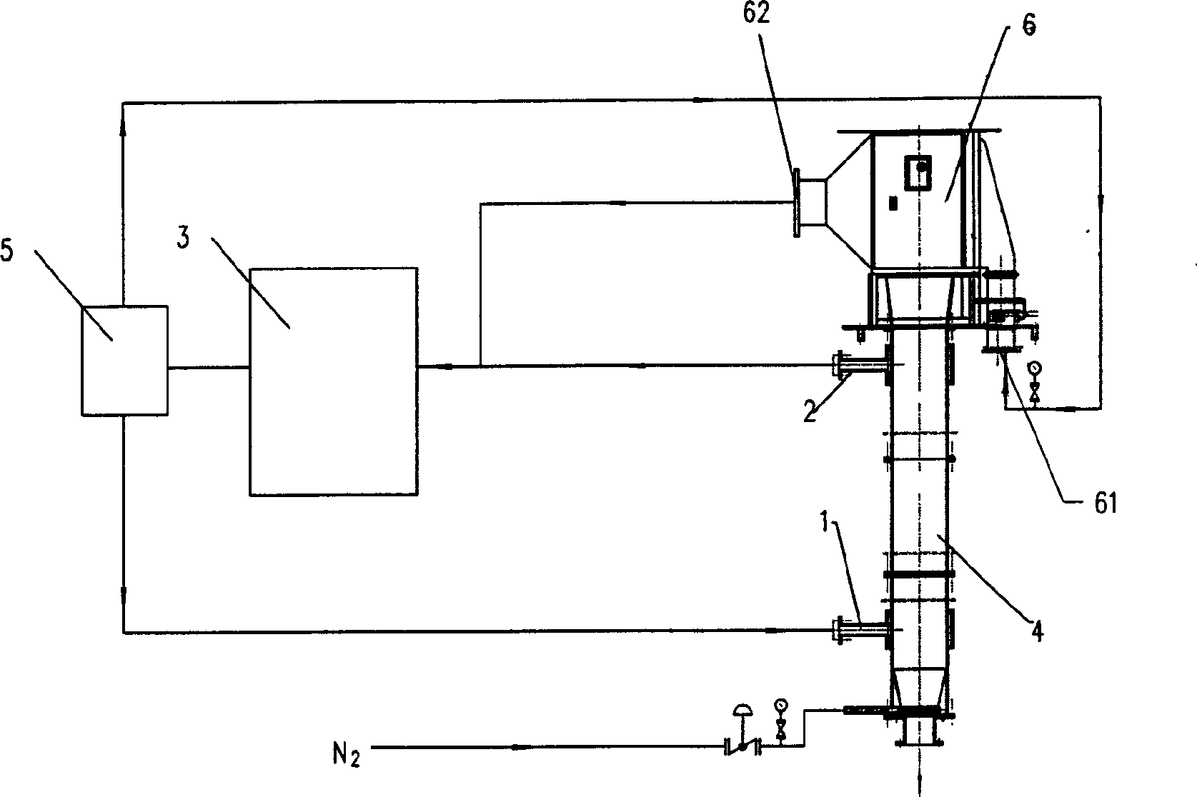
[0020] Embodiment one, see figure 1 , the figure shows a dry spinning hot air circulation device, which includes a tunnel 4, a solvent recovery device 3, and a heat exchanger 5. The tunnel 4 is respectively provided with a hot gas inlet 1 and an outlet 2, and the inlet 1 is located at the bottom of the tunnel 4. Below, the outlet 2 is located above the shaft 4; a side blowing device 6 is provided between the upper end of the shaft 4 and the spinneret, and two opposite sides of the side blowing device 6 have an inlet 61 and an outlet 62. The outlet of the solvent recovery device 3 is connected to the tunnel gas inlet 1 and the inlet 61 of the side blowing device through the heat exchanger 5, and the inlet of the solvent recovery device 3 is connected to the tunnel gas outlet 2 and the outlet 62 of the side blowing device.
[0021] Wherein the solvent recovery device 3 belongs to the prior art, and the gas that comes out through the gas outlet 2 of the tunnel 4 and the outlet 6...
Embodiment 2
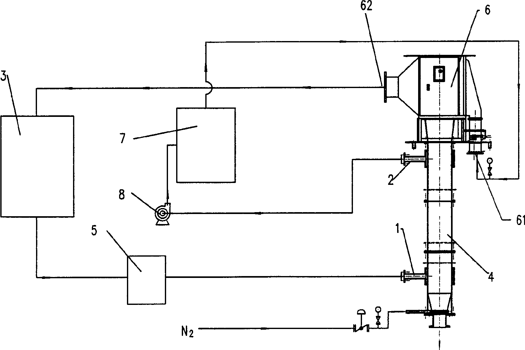
[0022] Embodiment two, see figure 2 , the figure shows a dry spinning hot air circulation device, including a tunnel 4, a solvent recovery device 3, and a heat exchanger 5. The tunnel 4 is respectively provided with a hot gas inlet 1 and an outlet 2, and the inlet 1 is located below the tunnel 4. , the outlet 2 is located above the shaft 4; at the outlet of the spinneret, the upper end of the shaft 4 is provided with a side blowing device 6, and the side blowing device 6 has an inlet 61 covering one side and an outlet 62 covering the other side and the outlet of the solvent recovery device 3 is connected to the tunnel gas inlet 1 through the heat exchanger 5, and the gas outlet 2 of the tunnel 4 is connected to the inlet 61 of the side blowing device; the inlet of the solvent recovery device 3 is connected to the outlet of the side blowing device 62 connected.
[0023] A heat exchanger 7 can be established between the entrance of the tunnel outlet 2 to the side blowing devic...
Embodiment 3
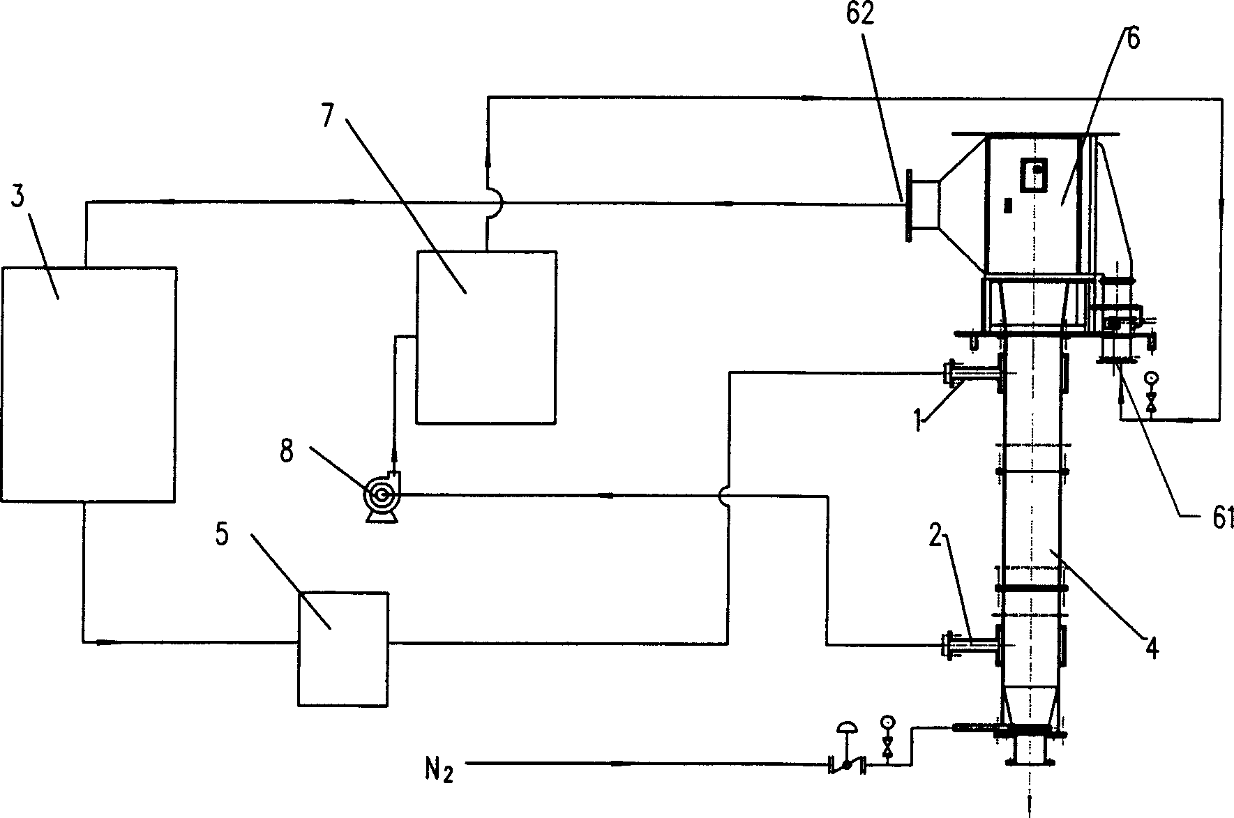
[0028] Embodiment three, see image 3 , the figure shows a dry spinning hot air circulation device, the difference from the previous embodiment is: the hot gas inlet 1 of the shaft 4 is located above the shaft 4, and the hot gas outlet 2 is located below the shaft 4. That is, the hot gas enters from the upper inlet 1 of the shaft 4, flows out from the outlet 2 below the shaft 4, and then is sent into the side blowing device 6. In this embodiment, the down-flow spinning and the side blowing device are combined in series Solvent evaporation and collection were performed.
PUM
 Abstract
Description
Claims
Application Information