Current equalizing method and apparatus for alternately controlling power factor correcting circuit

A power factor correction and control circuit technology, which is applied in the direction of output power conversion device, DC power input conversion to DC power output, control/regulation system, etc., can solve the problems of current imbalance, complicated circuit and complex control circuit, etc.

Active Publication Date: 2005-03-09
DELTA ELECTRONICS INC
View PDF1 Cites 32 Cited by
  • Summary
  • Abstract
  • Description
  • Claims
  • Application Information

AI Technical Summary

Problems solved by technology

On the other hand, however, this circuit structure has its problems: (1) the circuit is relatively complex; (2) due to the discrete nature of the two groups of components, the current between the two branches is unbalanced, especially when the entire device operates at This phenomenon is more serious when the inductor cu

Method used


Image

  • Current equalizing method and apparatus for alternately controlling power factor correcting circuit
  • Current equalizing method and apparatus for alternately controlling power factor correcting circuit
  • Current equalizing method and apparatus for alternately controlling power factor correcting circuit

Examples


Embodiment Construction

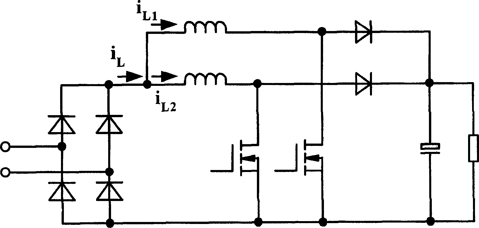
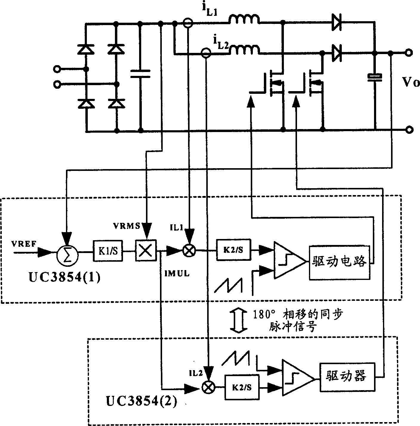
[0031] The control scheme adopted by the present invention is: sampling the inductance currents of two parallel units separately, adopting the average current control method, and controlling two power switches by two control chips (such as UC3854). Different from the aforementioned current sharing method, the two control chips here share the same current reference IMUL, such asfigure 2 Shown.

[0032] The two control chips share a current reference to ensure that the inductor current of each circuit is basically equal to achieve the purpose of current sharing. After the common control chip UC3854 is used for control, the inductor current of each circuit can track the rectified voltage well, and the average value of the inductor currents of the two circuits is the same, so the total inductor current can also track the rectified voltage well to ensure high Power factor. At the same time, the two UC3854s use two interleaved signals staggered by 180° to desynchronize, so that the pha...


PUM


Abstract

This invention proves a uniform current method and a device for stagger-controlling power-factor correcting circuit which samples induction currents of two parallel units and applies a uniform current control method that two control chips control two power switches separately and share one primary current to guarantee induction current of each path the same to realize the uniform current.

Description

(1) Technical field [0001] The present invention is a current sharing method and device for interleaving control power factor correction circuits, especially a control circuit applied to a parallel boost type power factor correction circuit current sharing. (2) Background technology [0002] The traditional BOOST type power factor correction device is widely used because of its simplicity, boost characteristics, and high efficiency. With the continuous improvement of the power level of the power supply, it is often necessary to use several such modular devices in series or parallel. For example, in high-voltage applications, a three-potential BOOST power factor correction circuit is often used to limit the voltage stress of the switching element to the output Half of the voltage, and in high-current applications, multiple BOOST converters are often used in parallel, and two parallel power factor correction devices such as figure 1 Shown. [0003] It consists of a bridge rectifie...

Claims


Application Information

Patent Timeline
IPC IPC(8): H02M1/14H02M3/28H02M3/335
CPCY02P80/10
Inventor 张庆友邱爱斌应建平曾剑鸿
Owner DELTA ELECTRONICS INC
Why Eureka
Try Eureka