Vacuum cleaner

A dust collector and vacuum technology, which is applied in the direction of vacuum cleaners, vacuum cleaner storage devices, suction filters, etc., and can solve problems such as interference and disturbance of vacuum cleaner curtain displays or paper

Inactive Publication Date: 2005-03-16
DYSON TECH LTD
View PDF0 Cites 7 Cited by
  • Summary
  • Abstract
  • Description
  • Claims
  • Application Information

AI Technical Summary

Problems solved by technology

The stream of exhaust air can also cause other problems, such as blowing out the pilot flame on the gas stove, disturbing curtains, other displays

Method used


Image

  • Vacuum cleaner
  • Vacuum cleaner
  • Vacuum cleaner

Examples


Embodiment Construction

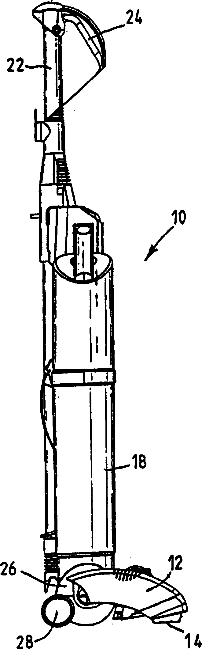
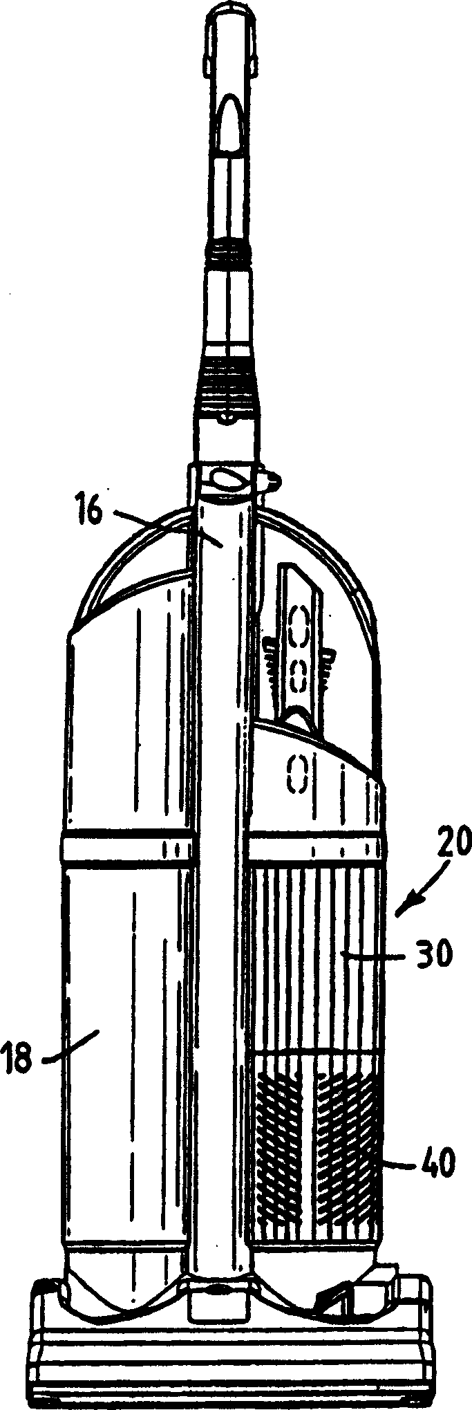
[0012] The vacuum cleaner of the present invention is shown in Figure 1a and Figure 1b middle. As can be seen, the vacuum cleaner 10 is an upright dust collector having a dust extraction head 12 which cooperates with an inlet 14 for dusty air. The central support 16 supports the dust separator 18 on one side and the filter element 20 on the other side. An upwardly extending handle 22 is located at the rear of the central support 16 and is in the form of a lever that is free to release when the vacuum cleaner is being used in cylinder mode. An upwardly extending handle 22 is connected to a handle 24 and has features other than those of the present invention. The dedusting head 12 is rotatably connected on the motor housing 26 , a motor is housed in the motor housing 26 and a pair of support wheels 28 are also connected on the motor housing 26 . In use, the motor draws dusty air into the vacuum cleaner 10 through the dusty air inlet 14 , or through the shaft 22 . The air t...


PUM


Abstract

The invention provides a vacuum cleaner comprising an airflow path having a dirty air inlet (14) and a clean air outlet (44e), a fan (48) for drawing an airflow along the airflow path from the dirty air inlet (14) to the clean air outlet (44e), a motor (50) for driving the fan (48), separating apparatus (18) for separating dirt and dust from the airflow, a pre-motor filter (32) arranged upstream of the motor (50) and a post-motor filter (42) arranged downstream of the motor (50), wherein both the pre-motor filter (32) and the post-motor filter (42) are cylindrical filters. The invention further provides a vacuum cleaner comprising an airflow path having a dirty air inlet (14) and a clean air outlet (44e), a fan (48) for drawing an airflow along the airflow path from the dirty air inlet (14) to the clean air outlet (44e), a motor (48) for driving the fan (50), separating apparatus (18) for separating dirt and dust from the airflow, a pre-motor filter (32) arranged upstream of the motor (50) and a post-motor filter (42) arranged downstream of the motor (50), wherein the post-motor filter (42) is housed in a casing (44) containing a plurality of slots or apertures (44e), the slots or apertures (44e) forming the clean air outlet and being arranged such that, in use, the aiflow is diffused as it leaves the clean air outlet.

Description

technical field [0001] The invention relates to a vacuum cleaner. Background technique [0002] A vacuum cleaner typically consists of: a dusty air inlet, a separator to separate the dust and dust from the airflow, a fan and motor to draw the airflow through the dusty air inlet into the separator, and discharge the cleaned air back into the separator. Atmospheric outlet. More typically, a pre-motor filter is placed upstream of the motor in the airflow path to prevent dust or debris still contained in the airflow from entering the motor. This reduces the risk of damage or wear to the motor due to dust or dust passing through the motor and also prevents this dust or dust from being re-emitted back into the atmosphere. It is also common to have an after-motor filter downstream of the motor to prevent any carbon particles shed from the motor, for example from the motor's brushes, from being expelled into the atmosphere with the airflow. These pre-motor and post-motor filters ...

Claims


Application Information

Patent Timeline
IPC IPC(8): A47L9/10A47L9/00A47L9/12A47L9/16
CPCA47L9/127A47L9/0081A47L5/28A47L5/32A47L9/0009
Inventor J·戴森
Owner DYSON TECH LTD
Why Eureka
Try Eureka