Cutting machine with improved wind shaft bracket

A technology of rewinding and slitting machine, applied in the field of machinery, can solve the problems of unstable running state of the reeling shaft, decline in product quality, increase in defective products, etc., to save maintenance time and cost, reduce labor intensity, and reduce processing difficulty Effect

Inactive Publication Date: 2005-03-16
周强
View PDF0 Cites 4 Cited by
  • Summary
  • Abstract
  • Description
  • Claims
  • Application Information

AI Technical Summary

Problems solved by technology

After the rewinding material is installed on the rewinding shaft bracket, in order to support the rewinding shaft bracket, the air cylinder needs to support the rewinding shaft bracket with air pressure all the time, and the gas is extremely unstable, that is, the pulsation of the air source, on the rewinding shaft During high-speed operation, there will be vibration of the winding shaft bracket, which will make the running state of the winding shaft unstable, affect the winding quality, and cause product loss
At the same time, since the cylinder is directly connected to one rewinding shaft bracket and connected to the other rewinding shaft bracket through the connecting rod, the two rewinding shaft brackets cannot operate synchronously, and errors will occur, and this asynchronous error belt The direct consequence is the decline in product quality, and even the increase in defective products, resulting in economic losses
In addition, the processing of the rewinding reel bracket has always been a difficult task. A slight mistake in the processing will affect the quality of the entire rewinding reel bracket, and even it can only be scrapped.
In addition, the loading and unloading of the winding shaft is also very laborious and labor-intensive
The above-mentioned problems have been unsolvable in the material slitting machine for many years, and the impact on the overall product quality is far greater than other factors

Method used


Image

  • Cutting machine with improved wind shaft bracket

Examples


Embodiment Construction

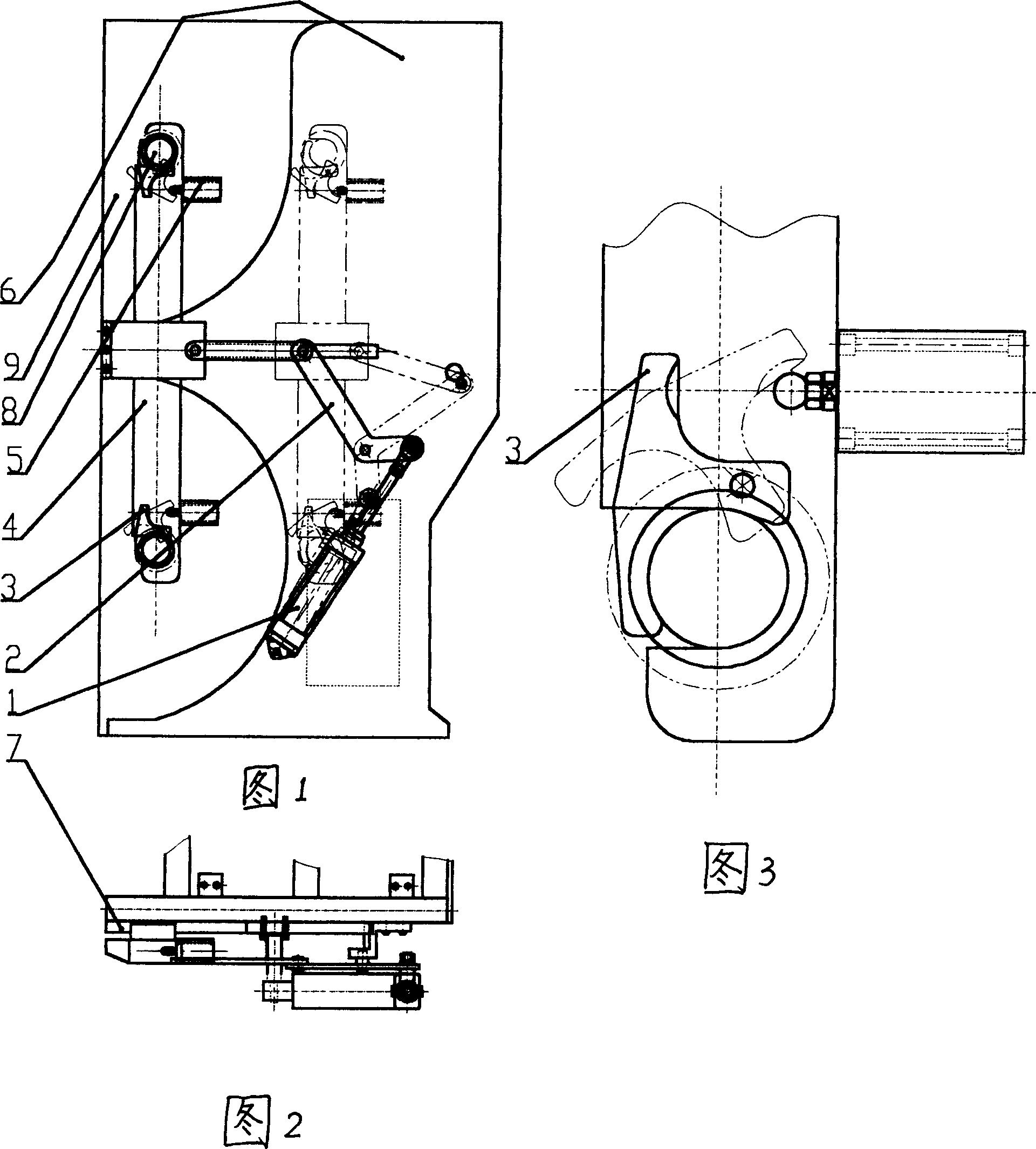
[0009] As shown in Figures 1, 2, and 3, the cylinder 1 is installed on the traction frame 6, and one end of the cylinder 1 is connected to one end of the connecting rod 2. The connecting rod 2 includes several connecting rod parts, and the combined connecting rod 2 is connected to the other end The rewinding shaft bracket 4, the rewinding shaft bracket 4 includes two brackets combined into one, and connected into one; upper translation, and the guide rail pair 7 is fixedly connected on the traction frame 6; two rewinding shafts 9 are carried at the two ends of the rewinding shaft bracket 4, and the clamping plate 3 is set here, and the clamping plate cylinder 5 is arranged on one side of the clamping plate 3 and connected with the the connection.

[0010] During work, original rewinding shaft bracket 4 does not contact with rewinding shaft 9, then connecting rod 2, rewinding shaft bracket 4 are all on the double-dot dash line position in Fig. 1; A), the cylinder 1 makes the c...


PUM


Abstract

This invention is about a sort of coiling shaft bearer in the splitting machine. This invention makes use of the air cylinder, connecting rod and guiding rail pair to fulfill the level shifting and supporting of the coiling shaft bearer, and it integrates the two bearers and fixes the coiling shaft by the bearer air cylinder and the snap-gauge. This invention can better solve such problems: only the air cylinder can move in a big curve the coiling shaft that must depend on the supporting bearer of the air cylinder, so it results in bad effect on the production quality because the unstable air in the air cylinder, that is, the air pulsation will shake the bearers. And the discord between the two bearers and support produce some irregularity that can damage the production quality. This invention is steady and reliable with a simple structure and secures the quality, and it largely reduces the difficulty of processing the bearers and its cost and the intensity of the upper and lower coils, so it is not easily damaged and can save much repairing expense.

Description

technical field [0001] The invention relates to a machine, in particular to a cutting machine for winding shaft brackets. Background technique [0002] Before the present invention, the rewinding shaft bracket on the existing slitting machine is connected with the connecting rod by the cylinder installed on the traction frame, the connecting rod is connected with one rewinding shaft bracket, and then another rewinding shaft is connected through another connecting rod bracket. After the rewinding material is installed on the rewinding shaft bracket, in order to support the rewinding shaft bracket, the air cylinder needs to support the rewinding shaft bracket with air pressure all the time, and the gas is extremely unstable, that is, the pulsation of the air source, on the rewinding shaft During high-speed operation, there will be vibration of the winding shaft bracket, which will make the running state of the winding shaft unstable, affect the winding quality, and cause prod...

Claims


Application Information

Patent Timeline
Patent Type & Authority Applications(China)
IPC IPC(8): B65H18/08B65H35/00
Inventor 周强
Owner 周强
Why Eureka
Try Eureka