Light-emission control circuit

A light-emitting control circuit and light-emitting element technology, applied to circuits, electroluminescence light sources, optics, etc., can solve problems such as no management, no management, and no consideration of changes in the deviation time of light source products

Inactive Publication Date: 2005-03-16
ROHM CO LTD
View PDF1 Cites 14 Cited by
  • Summary
  • Abstract
  • Description
  • Claims
  • Application Information

AI Technical Summary

Problems solved by technology

In the aforementioned Patent Document 1, light unevenness is reduced by using a light guide plate, but how much unevenness actually occurs is not managed.
Also, does not take into account product variations and changes over time of the light source
Even though the light is even, it doesn

Method used


Image

  • Light-emission control circuit
  • Light-emission control circuit
  • Light-emission control circuit

Examples


Embodiment approach 1

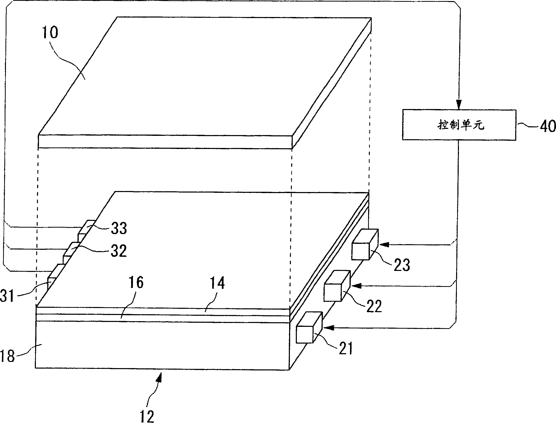
[0022] figure 1 The overall configuration of the light emission control circuit used in the liquid crystal display device of the first embodiment is schematically shown. The liquid crystal display device has a liquid crystal panel 10 and a backlight unit 12. The liquid crystal panel 10 may be any liquid crystal panel if it is a transmissive or semi-transmissive liquid crystal panel, such as TN (Twist Nematic) liquid crystal, STN (Super Twist Nematic) liquid crystal, TFT (Thin-film Transistor) liquid crystal, and the like. Since it is well known, the structure of the liquid crystal panel 10 itself is not shown in detail, but as an example, starting from the side close to the backlight unit 12, follow the polarizing filter, glass or plastic substrate, transparent electrode, alignment film, liquid crystal material, alignment The film, the transparent electrode, the color filter, the glass substrate, and the polarizing plate are arranged in order, and the liquid crystal material is ...

Embodiment approach 2

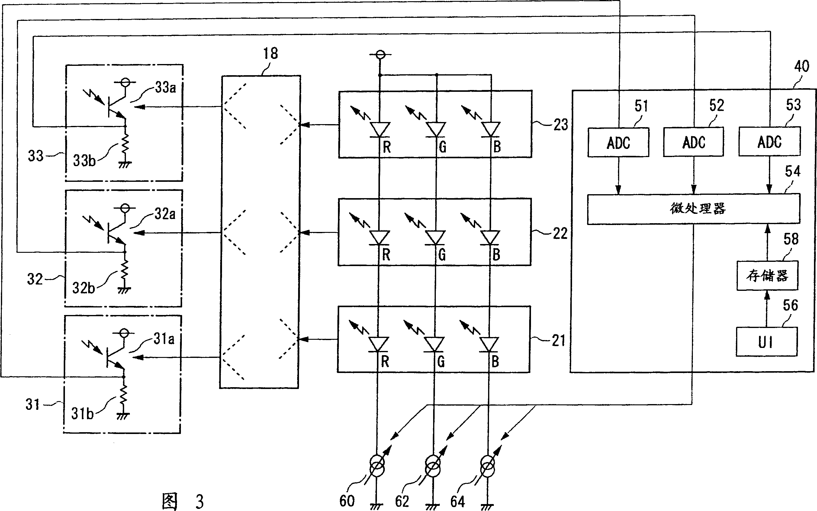
[0038] FIG. 3 schematically shows the overall configuration of a light emission control circuit used in a liquid crystal display device according to the second embodiment. Hereinafter, the same reference numerals are given to the same structures as those in FIG. 2 and the description is omitted, and the description will be focused on the parts different from those in FIG. 2.

[0039] As shown in FIG. 3, in the second embodiment, the R filter 31c, the G filter 32c, and the B filter are removed from the first light receiving section 31, the second light receiving section 32, and the third light receiving section 33 of the measurement unit, respectively. The device 33c, the first phototransistor 31a, the second phototransistor 32a, and the third phototransistor 33a directly detect the light from the light guide plate 18. In addition, the microprocessor 54 does not separately but collectively controls the first constant current source 60, the second constant current source 62, and the...

Embodiment approach 3

[0043] FIG. 4 schematically shows the overall configuration of the light emission control circuit used in the liquid crystal display device of the present embodiment. Hereinafter, the same reference numerals are given to the same structures as those in FIG. 3 and the description is omitted, and the description will be focused on the parts different from those in FIG. 3.

[0044] As shown in FIG. 4, in the third embodiment, the first light receiving unit 31, the second light receiving unit 32, and the third light receiving unit 33 of the measurement unit are replaced with a single first light receiving unit 31. Corresponding to this, the first A / D converter 51, the second A / D converter 52, and the third A / D converter 53 also become the only first A / D converter 51. The microprocessor 54 overall controls the first constant current source 60, the second constant current source 62, and the third constant current source 64. In the ROM of the memory 58, only one reference value represent...


PUM


Abstract

A light-emission control circuit may include n light-emitting devices, where n is an integer equal to or greater than 2; a light guide plate which causes light emitted by the n light-emitting devices to reach the entirety of the back of a liquid crystal panel; a measuring unit for measuring a luminance of the entirety of the n light-emitting devices operating in the liquid crystal panel; and a control unit for comparing the measured luminance with a predetermined value and controlling the luminance of the n light-emitting devices, based on a result of comparison, wherein the n light-emitting devices are attached to a side of the light guide plate, and the measuring unit is attached to an opposite side of the light guide plate.

Description

Technical field [0001] The present invention relates to a light emission control circuit, and more specifically, to a circuit that controls the light emission of a light emitting element that illuminates a liquid crystal panel. Background technique [0002] In notebook personal computers and various portable terminals, liquid crystal display devices are widely used. A liquid crystal display device is a device that illuminates the liquid crystal panel from the back with a backlight, and uses the light blocking and transmission phenomenon caused by the interaction of the liquid crystal and the polarizing filter to obtain the required display. Generally, it helps to reduce power consumption. It is considered that it will continue to be a mainstream display device in the future. [0003] In the case of a personal computer, on the one hand, space for the light source can be secured to a certain extent, on the other hand, fluorescent tubes, which are linear light sources, which can irr...

Claims


Application Information

Patent Timeline
IPC IPC(8): G02F1/13357F21S2/00F21S8/04F21V8/00F21Y101/02G01J1/32G02F1/133G02F1/1335G09G3/14G09G3/20G09G3/34G09G3/36H05B44/00
CPCG09G2360/145G02B6/0068G01J1/32G09G2320/0233G09G2320/064G09G2320/0666G09G3/3413H05B45/22G02F1/133
Inventor 山本勋宫长晃一
Owner ROHM CO LTD
Why Eureka
Try Eureka