Machining centre

A machining center and process technology, applied in metal processing equipment, metal processing machinery parts, manufacturing tools, etc., can solve the problems of time-consuming and low productivity

Inactive Publication Date: 2005-03-23
YAMAZAKI MAZAK KK
View PDF1 Cites 15 Cited by
  • Summary
  • Abstract
  • Description
  • Claims
  • Application Information

AI Technical Summary

Problems solved by technology

[0009] However, in the case of the above-mentioned armless tool automatic changing device, since the movement U and stop of the main shaft 111 (refer to FIG. 8 ), and the movement B and stop of the tool

Method used


Image

  • Machining centre
  • Machining centre
  • Machining centre

Examples


Embodiment Construction

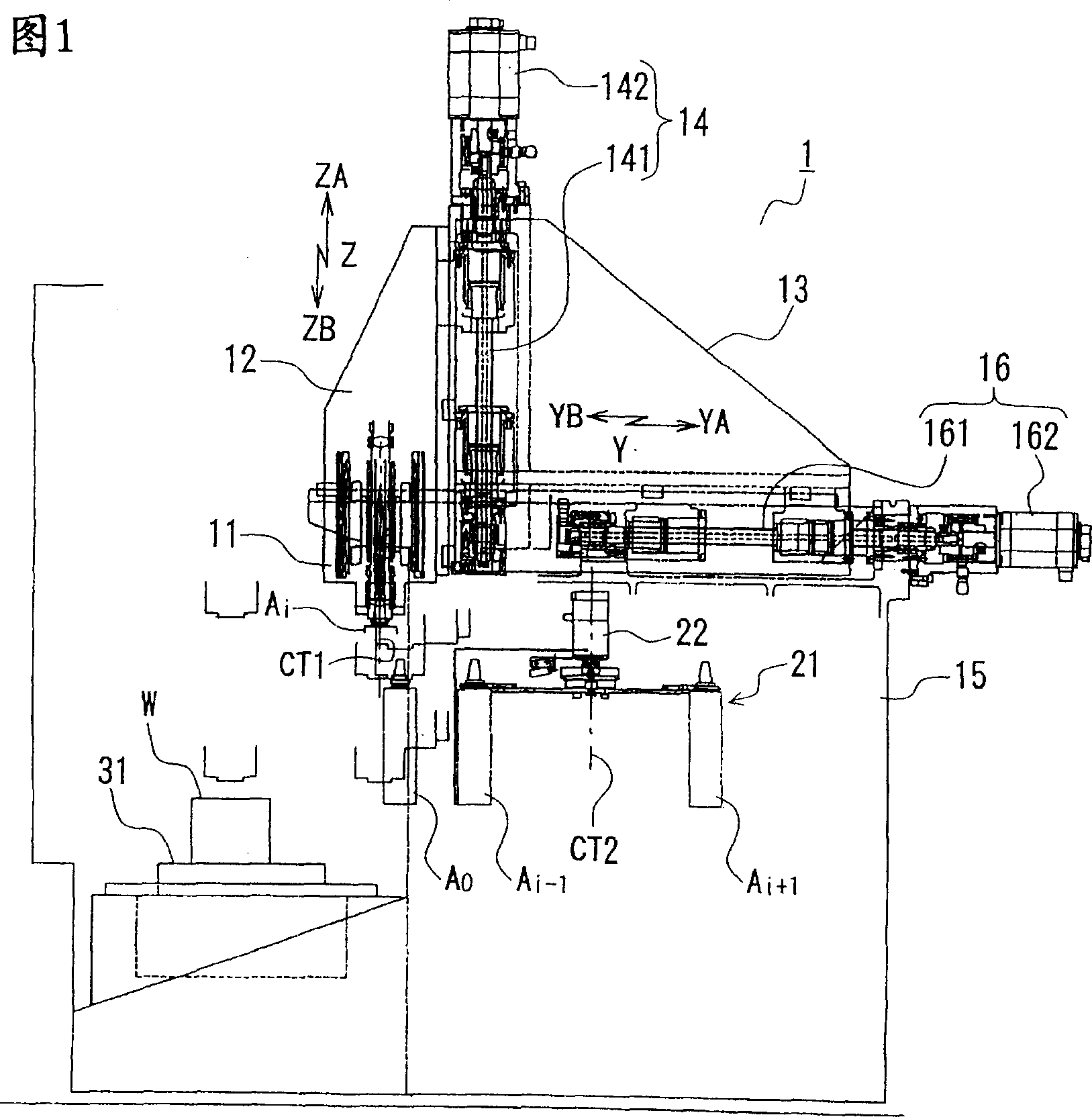
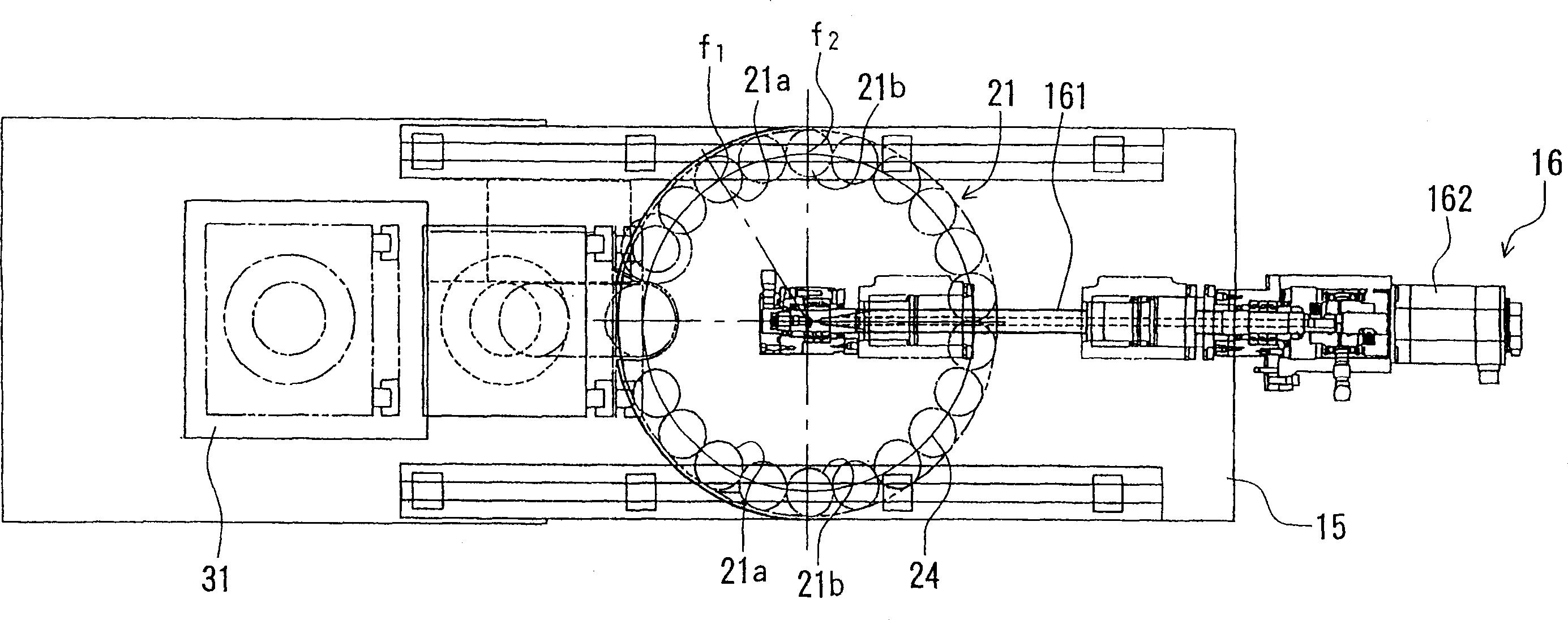
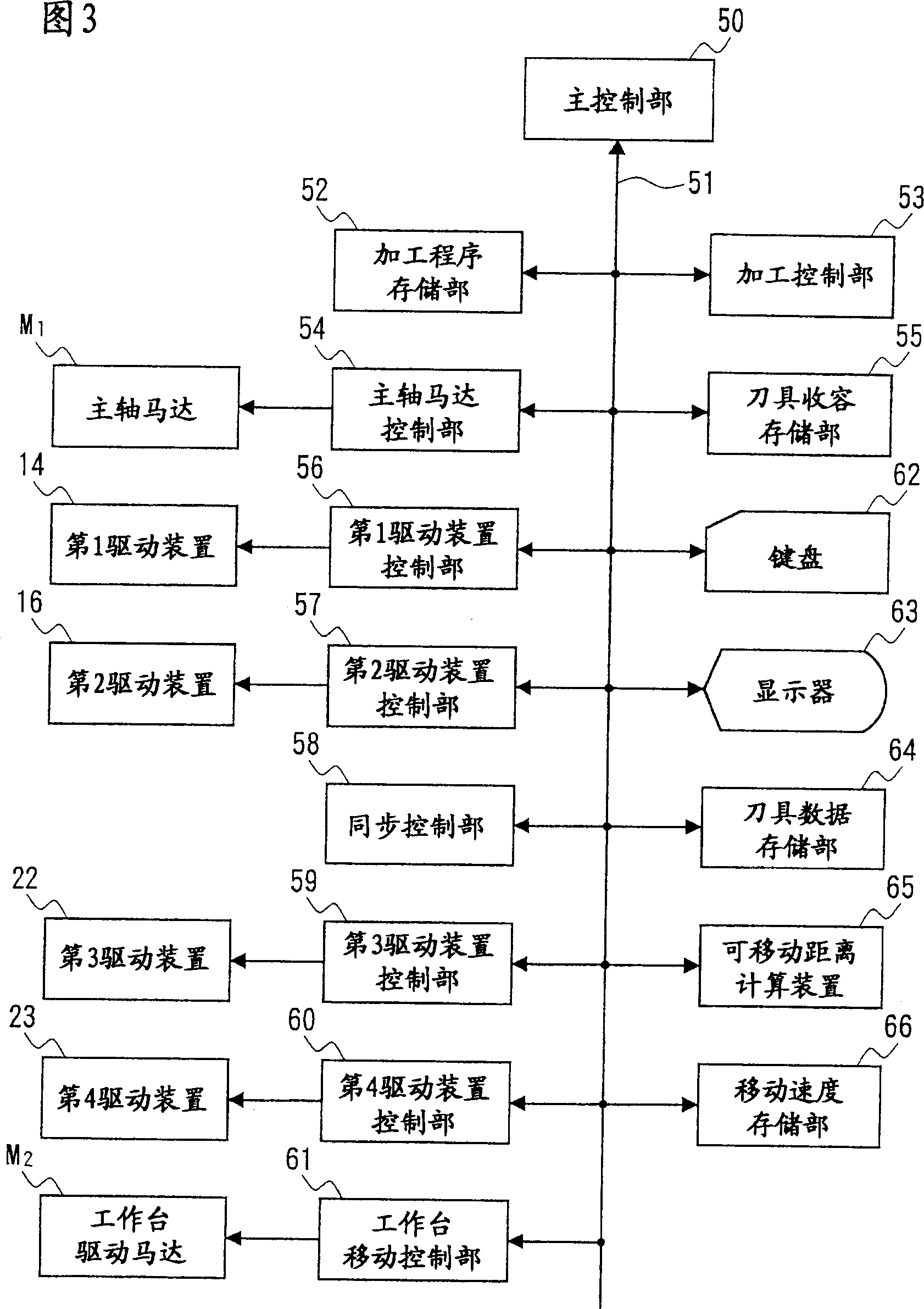
[0031] Fig. 1 is a side view showing an example of the structure of the machining center in the present invention; figure 2 It is a plan view showing an example of the structure of the machining center in the present invention; FIG. 3 is a block diagram showing an example of the structure of the control device of the machining center in the present invention; A schematic diagram of the state in which the tool is removed and stored in the tool magazine; Figure 5(a)-(e) is a schematic diagram showing the state of the tool magazine moving; Figure 6 (a) to (e) are schematic diagrams showing a state in which a tool is mounted on a spindle.

[0032] As shown in FIG. 1, a machining center 1 in the present invention has a spindle 11 that detachably supports a tool Ai (only the upper part is shown), and a plurality of tool holders for accommodating the tools Ai-1 and Ai+1. (refer to figure 2 In the label 21a, 21b) tool magazine 21. As shown in Figure 4 (a), in the tool magazine 2...


PUM


Abstract

When exchanging a tool, a tool of a spindle is stored in an empty pocket of a tool magazine, and thereafter, upward movement of the spindle and rotation of the tool magazine are simultaneously executed. At this time, synchronous control is performed in order to prevent a collision between the spindle and the tool. When installing a next tool in the spindle, both downward movement of the spindle and rotation of the tool magazine are executed while synchronously controlling. The tool exchange time can be shortened with simultaneously executing the movements of the spindle and the tool magazine.

Description

technical field [0001] The present invention relates to a machining center capable of machining a workpiece while appropriately changing tools, and more specifically, to a machining center equipped with a so-called armless automatic tool changer. Background technique [0002] The machining center has a table on which a workpiece is placed, a spindle that drives a supported tool to process the workpiece, and an automatic tool changer that automatically replaces the tool on the spindle, and is configured so that the workpiece can be machined by appropriately replacing the tool. As the automatic tool changing device, there can be exemplified an ATC arm or a moving frame or an ATC arm driving unit (armed automatic tool changing device), and a tool is performed only by the movement and positioning of the tool magazine and the spindle without the ATC arm. Changing armless automatic tool changer. [0003] Compared with the arm type of the former, the latter armless type is charact...

Claims


Application Information

Patent Timeline
IPC IPC(8): B23Q3/155B23Q3/157
CPCB23Q3/15526B23Q3/15706Y10T483/1736Y10T483/1795Y10T483/132Y10T483/10B23Q2003/15537
Inventor 户冢美树夫乘松途夫小池治彦笼桥秀义
Owner YAMAZAKI MAZAK KK
Why Eureka
Try Eureka