Cylinder of IC engine
A technology for cylinder blocks and internal combustion engines, applied to cylinders, cylinder heads, mechanical equipment, etc., can solve problems such as adverse effects and increase solidification time, reduce gas consumption, reduce oil consumption, and prevent thermal deformation or shrinkage Effect
Inactive Publication Date: 2010-12-01
HONDA MOTOR CO LTD
View PDF0 Cites 0 Cited by
- Summary
- Abstract
- Description
- Claims
- Application Information
AI Technical Summary
Problems solved by technology
The existence of the above-mentioned wide and thick-walled cast part in the light alloy of the cylinder block makes the wall thickness of the light alloy cast part such as aluminum alloy covering the outer peripheral part of the cylinder liner inconsistent. The expansion of the uniformity increases the time difference of the solidification time of the light alloy casting part such as aluminum alloy during the casting of the cylinder block. shrinkage, thermal deformation will remain, and since the light alloy casting part acts on the cylinder liner covering its outer peripheral part, an uneven force will act on the cylinder liner, which will have an adverse effect
Method used
View moreImage
Smart ImageViewing Examples
Examples
Embodiment 1
Embodiment 2
Login to View More PUM
 Abstract
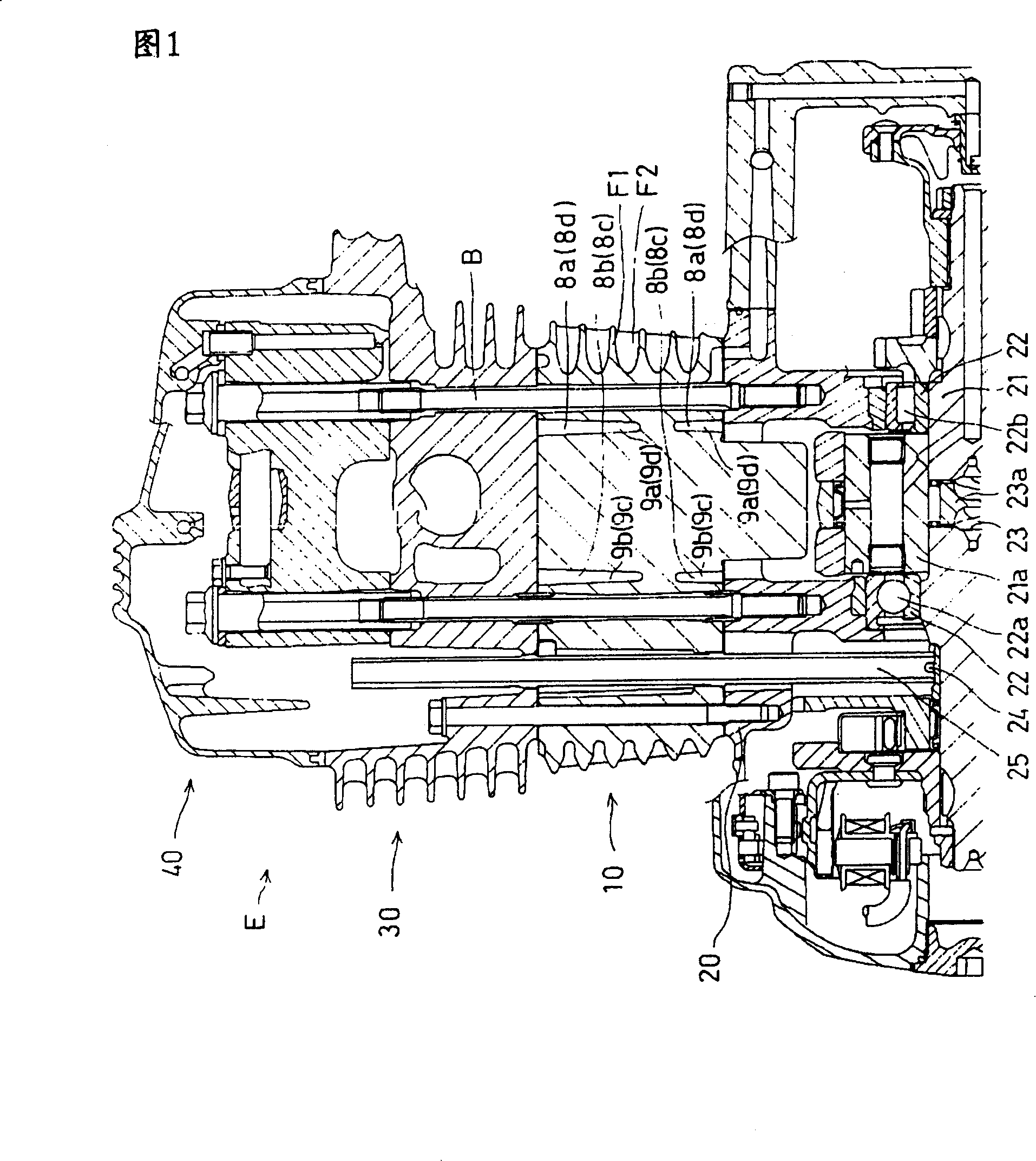
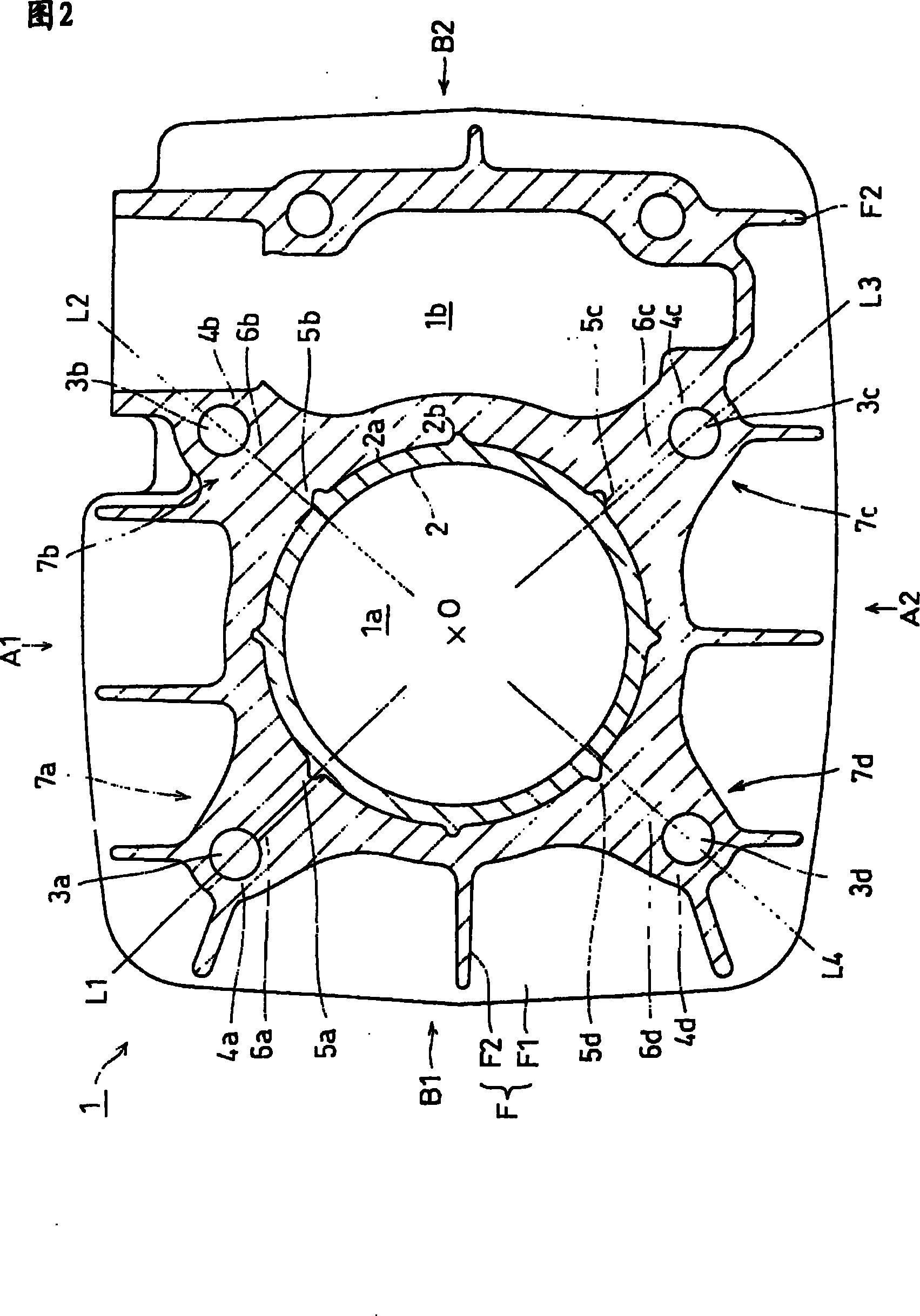
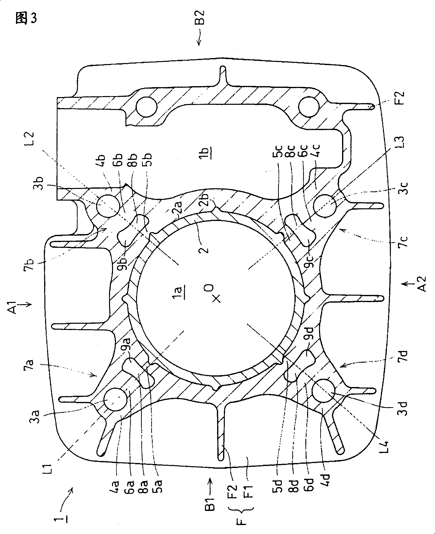
To equalize force holding a sleeve, by uniformizing wall thickness of cast thick parts of a cast cylinder block to eliminate solidifying time difference between cast thick parts in casting, in the cast cylinder block made from light alloy with which a sleeve is cast integrally. The iron cylinder sleeve 2 is cast integrally with an aluminum alloy cylinder block 1, and bolt holes 3a to 3d for tightening the cylinder block 1 are formed in an aluminum casting part covering an outer peripheral part 2a of the sleeve. Connection parts are wide and thick cast connection parts 6a to 6d and connects surrounding parts of the bolt holes 3a to 3d with the outer peripheral part 2a of the sleeve. Thinned parts 8a to 8d are formed in the wide and thick cast connection parts 6a to 6d to uniformize the wall thickness of the aluminum casting part covering the peripheral part 2a of the sleeve.
Description
Cylinder block for internal combustion engine technical field The present invention relates to a cylinder block for an internal combustion engine, and in particular to an improvement technology for a cylinder block of an air-cooled internal combustion engine. out of shape. Background technique The general shape of the cylinder block for internal combustion engines is shown in the perspective view of Figure 7. In most cases, light alloys such as aluminum alloys are used to integrally cast iron (cast iron) cylinder liners with circular cross-sections, or iron ( Cast iron) cylinder liners are press-fitted into cylinder bodies cast from light alloys such as aluminum alloys. The influence of the homogenization of the wall thickness has not been adequately considered. Generally, the periphery of the fixing bolt hole for fastening the crankcase and cylinder head of the cylinder block is provided as a cast part with increased rigidity for fastening, especially the position from...
Claims
Login to View More Application Information
Patent Timeline
 Patent Type & Authority Patents(China)
IPC IPC(8): F02F1/08F02F1/00F02F1/24
Inventor 神户敬司水谷文则小林修二
Owner HONDA MOTOR CO LTD
Features
- R&D
- Intellectual Property
- Life Sciences
- Materials
- Tech Scout
- Unparalleled Data Quality
- Higher Quality Content
- 60% Fewer Hallucinations
Learn More Browse by: Latest US Patents, China's latest patents, Technical Efficacy Thesaurus, Application Domain, Technology Topic, Popular Technical Reports.
© 2025 PatSnap. All rights reserved.Legal|Privacy policy|Modern Slavery Act Transparency Statement|Sitemap|About US| Contact US: help@patsnap.com


