Three-dimensional vibrating composite damper of engine axis for vehicle

A vehicle engine, three-dimensional vibration technology, applied in the direction of rotational vibration suppression, etc., can solve the problem of a single vibration damping direction of the shock absorber, and achieve the effects of reducing shaft vibration, noise, and noise radiation.

Inactive Publication Date: 2005-03-23
TIANJIN UNIV
View PDF0 Cites 8 Cited by
  • Summary
  • Abstract
  • Description
  • Claims
  • Application Information

AI Technical Summary

Problems solved by technology

[0003] In order to overcome the above-mentioned shortcoming of the single damping direction of the shock absorber and the difficult parameter optimization problem in the design of the shock absorber that takes into account the multi-dimensional damping effect, the purpose of the present invention is to propose a three-dimensional vibration (torsional vibration, bending vibration, longitudinal vibration) compound shock absorber, which can reduce the vibration and noise of the internal combustion engine to a minimum

Method used


Image

  • Three-dimensional vibrating composite damper of engine axis for vehicle
  • Three-dimensional vibrating composite damper of engine axis for vehicle
  • Three-dimensional vibrating composite damper of engine axis for vehicle

Examples


Embodiment 1

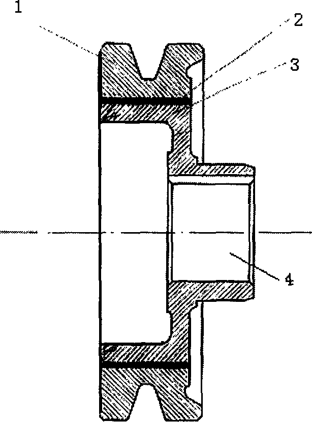
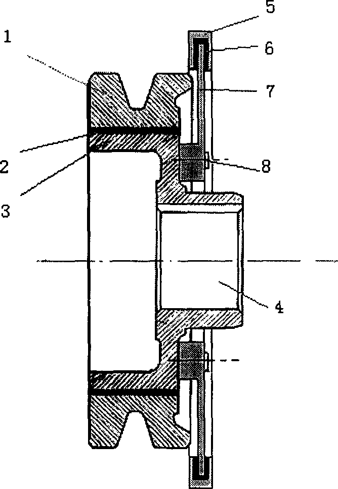
[0023] Example 1, for figure 2 In the shown structural form, the torsional vibration rubber layer 2 is molded and installed between the torsional vibration outer hub 1 and the torsional vibration inner hub 3 through a press-fit process. The rubber layer is formed by a mold, and is installed between the longitudinal bending inertia block 5 and the longitudinal bending inner hub 7 by a vulcanization process. The longitudinal bending inner hub 7 of the longitudinal and bending damper is connected with the torsional vibration inner hub 3 of the torsional vibration damper by bolts 8 to form a composite damper.

Embodiment 2

[0024] Example 2, for Figure 5 In the structural form shown, the torsional vibration rubber layer 2 is molded through a mold, and installed between the longitudinal bending inertia block 5 , the torsional vibration inner hub 3 and the sealing ring 9 by a vulcanization process. The sealing ring 9 is installed on the torsional vibration inner hub 3 through bolts. The torsional vibration rubber layer 2 is molded and installed between the torsional vibration outer hub 1 and the torsional vibration inner hub 3 through a press-fit process.

Embodiment 3

[0025] Example 3, for Image 6 In the structural form shown, the torsional vibration rubber layer 2 is molded and installed between the longitudinal bending inertia block 5 and the torsional vibration inner hub 3 by vulcanization process. The rubber layer 2 is molded and installed between the torsional vibration outer hub 1 and the torsional vibration inner hub 3 through a press-fit process.

[0026] The damping effects of the present invention on bending vibration and longitudinal vibration are shown in Table 1 and Table 2 respectively.

[0027] 3 times

4 times

4.5 times

5 times

6 times

7 times

7.5 times

9 times

175Hz

11

5.5

23

7

4.5

3.8

4.5

2.4

225Hz

12

7

6

6

3.5

2.5

2.2

0.9

275Hz

11

6

5

6

4

2.8

3

1.2

original machine

23

11

...


PUM


Abstract

The invention relates to a technique of automobile engine vibration reduction and noise reduction. Its main technical characteristic all are made up of torsion vibration damper and longitudinal-direction-bend damper; rubber layer is nests between the outside hub and inside hub, the torsion vibration damper is made up of torsion vibration outside hub, torsion vibration rubber layer, and torsion vibration inside hub; longitudinal bending bowing inertia block is connected to the longitudinal bending bowing inside hub through the rubber layer, and made up of longitudinal-direction-bend vibration damper; compound damper is made up of the torsion vibration damper and the longitudinal-direction-bend vibration damper connected by bolt; we can equip the longitudinal bending bowing inertia block in the cavity of the inside hub, its left end is cling to the rubber layer, the outside is sealed by seal ring to form the longitudinal-direction-bend damper; we also can equip the rubber layer between the torsion vibration inside hub and the longitudinal bending bowing inertia block to form the longitudinal-direction-bend vibration damper.

Description

technical field [0001] The invention specifically relates to a technology for reducing vibration and noise of an automobile engine. Background technique [0002] When the internal combustion engine is working, the crankshaft not only bears the effects of gas pressure and inertial force, but also outputs the torque on each crank throw to drive other mechanical parts to rotate and do work. Therefore, in addition to the torsional moment, the crankshaft also bears the bending force. Due to the structural characteristics and working characteristics of the crankshaft and crank connecting rod, under the action of the above excitation force, the vibration form of the crankshaft is a combination of torsional vibration, bending vibration and longitudinal vibration. In the structure of the internal combustion engine, the crankshaft is installed on the skirt under the body, and the main bearing of the crankshaft is fixed by the main bearing. The multi-form ...

Claims


Application Information

Patent Timeline
Patent Type & Authority Applications(China)
IPC IPC(8): F16F15/12
Inventor 舒歌群梁兴雨卫海桥吕兴才
Owner TIANJIN UNIV
Why Eureka
Try Eureka