Circuit breaker

A circuit breaker and dynamic contact technology, which is applied in the direction of circuit breaker parts, circuit breaker contacts, circuits, etc., can solve the problems of decreased circuit breaker characteristics, decreased circuit breaker performance, difficulties, etc., and achieves suppression of contact pressure, high circuit breaker performance, and structure brief effect

Inactive Publication Date: 2005-03-23
FUJI ELECTRIC FA COMPONENTS & SYST CO LTD
View PDF5 Cites 4 Cited by
  • Summary
  • Abstract
  • Description
  • Claims
  • Application Information

AI Technical Summary

Problems solved by technology

[0016] However, in the above-mentioned conventional springback prevention strategy for the movable contact, in addition to the complicated structure of the contact holder and the increase in the number of parts, there is also an increase in the mass of the movable mechanism including the contact holder that will hinder the electromagnetic force. Problems such as degradation of breaking performance due to high-speed operation of repulsive force
However, the driving spring of the movable contact has the structure of Patent Document 4 using a lock spring. Although it can be handled by a simple structure, the spring characteristics are actually reversed in accordance with the opening and closing operations of the movable contact. It is difficult, and in the middle of moving the movable contact towards the closed pole / open pole position, because a considerable force is required to reverse the lock spring, it is possible to make the pole open due to the electromagnetic repulsion of the overcurrent. The opening speed of the movable contact is slowed down and the breaking characteristics are reduced

Method used


Image

  • Circuit breaker
  • Circuit breaker
  • Circuit breaker

Examples


Embodiment 1

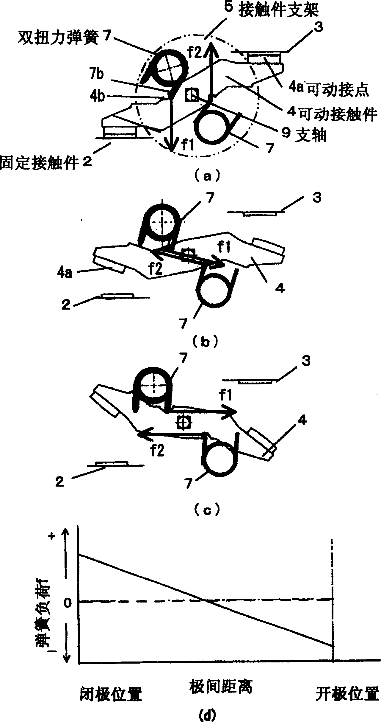
[0038] figure 1 (a) to (d) show examples corresponding to two aspects of the present invention. In this embodiment, although the current breaking part is basically the same as the structure of FIG. 5, as the contact pressure spring of the movable contact 4, two sets of double torsion springs 7 equipped on the contact holder 5 are arranged as follows . That is, the double torsion springs 7 arranged above and below the movable contact 4 are arranged to be axially symmetrical with respect to the support shaft 9 provided at the rotation center of the movable contact 4, and the double torsion springs 7 are displaced from the double torsion The displacement arm portion 7b protruding from the center of the spring 7 is shorter than the structure shown in FIG.

[0039] With this structure, in figure 1 In the closed pole position of (a), the spring loads f1 and f2 of the double torsion spring 7 work on the movable contact piece 4 as a force couple, and press the movable contact pie...

Embodiment 2

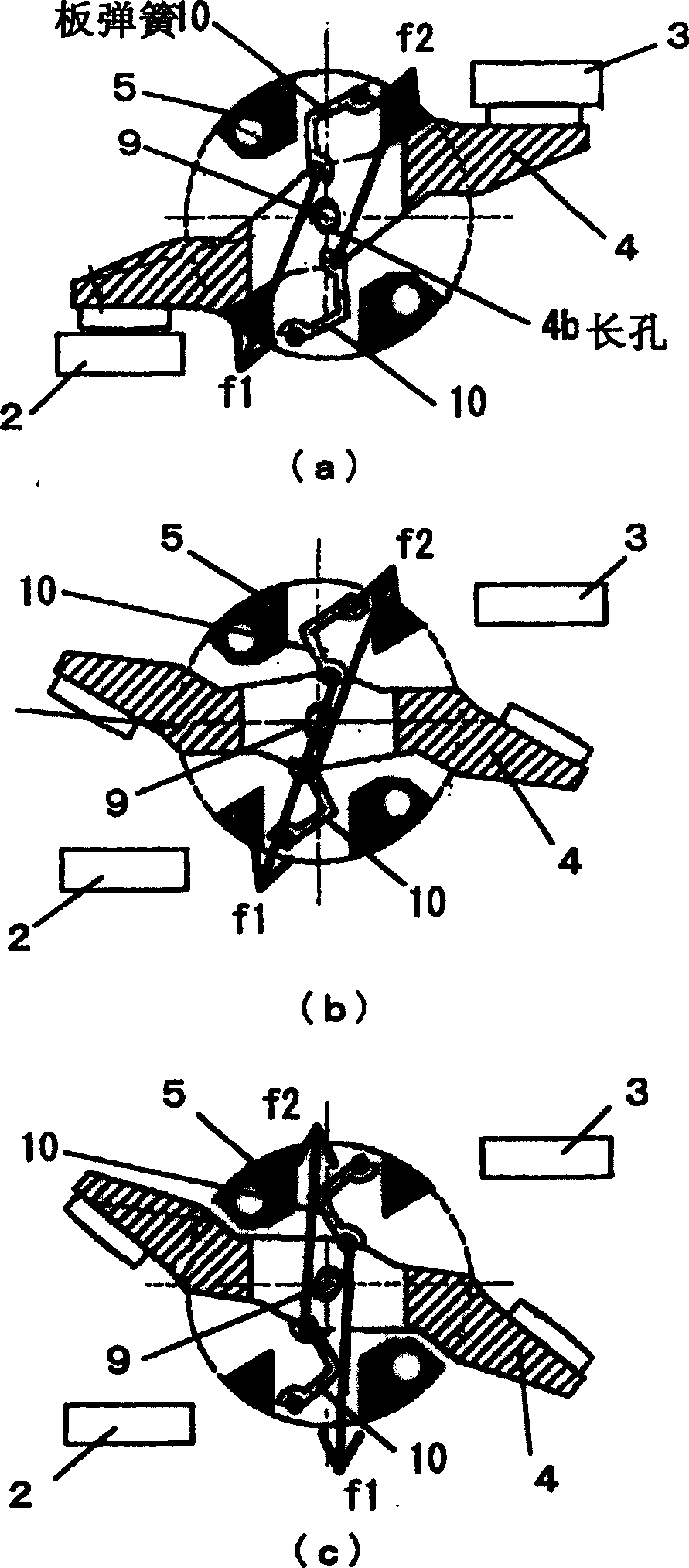
[0043] Then the embodiments corresponding to the 3rd and 4th aspects of the present invention are as follows figure 2 (a) ~ (c) shown. In this embodiment, the double torsion spring 7 of the foregoing embodiment 1 is replaced with a leaf spring 10 with a simple structure, and two sets of leaf springs 10 are mounted on the movable contact piece 4 in a deflected state as shown in the figure. Between the back of the upper and lower sides and the contact bracket 5, in figure 2 In the closed position of (a), the contact of the movable contact 4 is pushed toward the fixed contact by the spring loads f1 and f2 of the plate spring 10 . In addition, although a shaft hole passing through the support shaft 9 is opened at the rotation center of the movable contact 4, the shaft hole is formed along a line connecting the engagement points of the two sets of leaf springs 10 and the movable contact 4. The long hole 4b.

[0044] With this structure, if the electromagnetic repulsion force g...

Embodiment 3

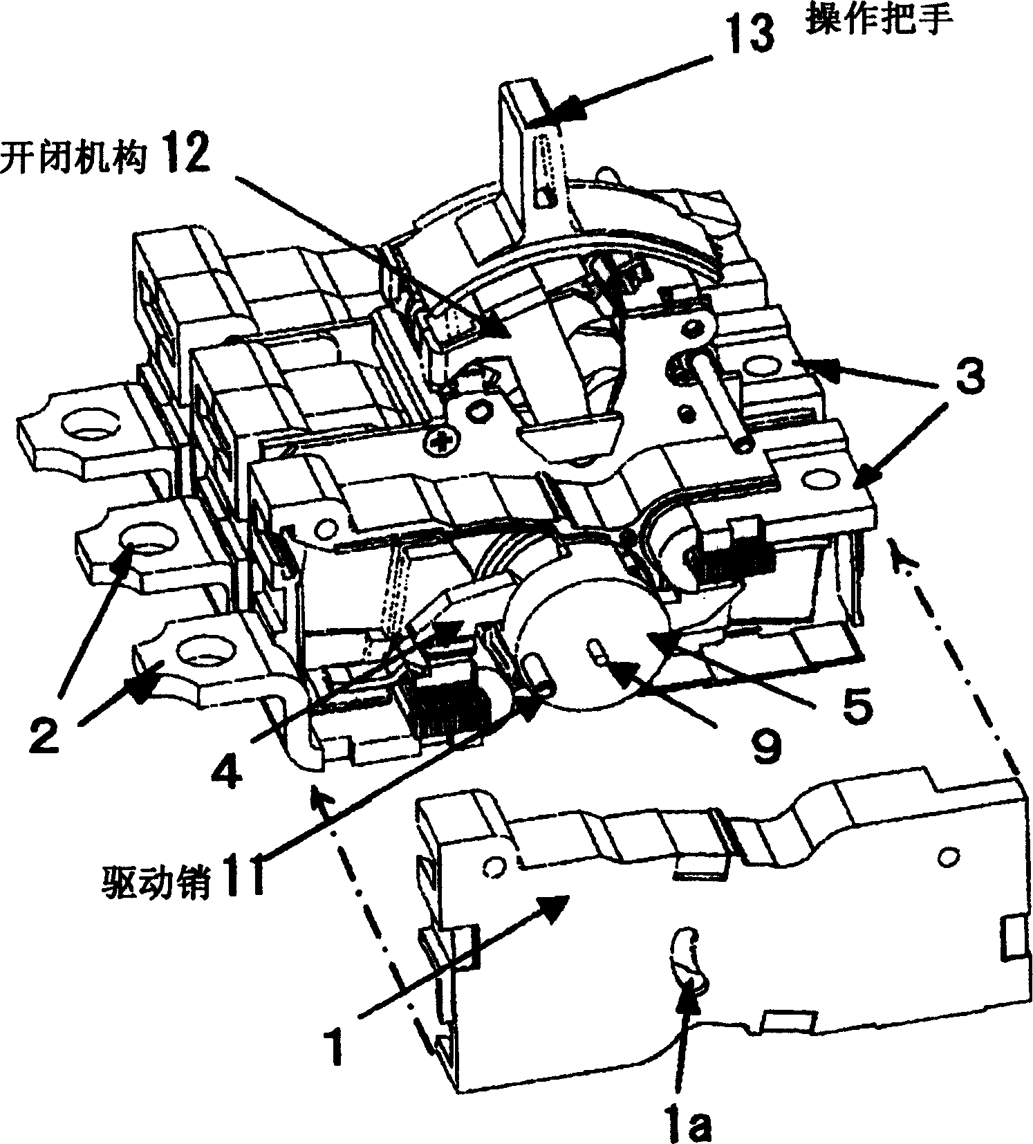
[0048] exist image 3 In this embodiment, the current breaking part of each phase constituting the 3-phase circuit breaker is a structure in which the support shaft 9 penetrating through the rotation center of the movable contact piece 4 and the support shaft of the contact sub-support 5 are used in the previous embodiment. .

[0049] That is, the support shaft 9 penetrates through the center of rotation of the contact holder 5, and its shaft end is supported by a bearing part (not shown) formed inside the case 1 (two-part structure) of the current interrupting part, so that the movable contact The member 4 and the contact member bracket 5 are pivotally supported possibly in rotation. Further, in addition to the above-mentioned support shaft 9, a common drive pin 11 is provided for each phase of the arc-shaped shaft hole 1a that penetrates the contact bracket 5 and the side wall surface of the housing 1, so that the drive pin 11 passes through in a left and right direction. ...


PUM


Abstract

PROBLEM TO BE SOLVED: To improve breaking performance by preventing a movable contactor from bouncing back from a pole-opening position with the use of a spring member built into a contactor holder as a pressure contact spring for the movable contactor.SOLUTION: The circuit breaker has a rotation system bridging type movable contactor 4 loosely retained by a contactor holder, and drives the movable contactor toward the pole-opening position with electromagnetic repulsive force acting between fixed contactors 2, 3 and the movable contactor when an overcurrent flows. Two sets of double-torsion springs 7 functioning as the pressure-contacting springs of the movable contactors are arranged at the contactor holder at axial symmetry around a rotation center of the movable contactor, and contact points of the movable contactor are pressed and biased toward a fixed contact point with a spring load of the spring member at a pole-closing position. A load working point of the double-torsion springs against the movable contactor is set at a position to bias the movable contactor toward a pole-closing direction in the vicinity of a pole-closing position, and to bias the movable contactor toward a pole-opening direction in the vicinity of the pole-opening position with a direction of a line of action of the spring load reversed.

Description

technical field [0001] The present invention relates to a circuit breaker such as an automatic circuit breaker, and more specifically, relates to the structure of its current breaking unit. Background technique [0002] As the above-mentioned circuit breaker, it is known that the current interrupting part adopts a bridge-shaped movable contact held by a rotary contact holder, and when an overcurrent is energized, an electromagnetic switch acting between the fixed contact and the movable contact is known. A circuit breaker of a two-contact switching type in which a movable contact is opened using a repulsive force as a driving force (for example, refer to Patent Document 1). [0003] In addition, in the current interrupting part of the above-mentioned circuit breaker, the contact pressure spring of the movable contact of the contact holder is arranged in combination with the movable contact (a predetermined voltage is applied between the movable contact and the fixed contact ...

Claims


Application Information

Patent Timeline
Patent Type & Authority Applications(China)
IPC IPC(8): H01H73/02H01H71/12H01H73/04
CPCH01H2001/223
Inventor 恩地俊行和田正义矶崎优
Owner FUJI ELECTRIC FA COMPONENTS & SYST CO LTD
Why Eureka
Try Eureka