Structure for reducing notice in vacuum cleaner

A vacuum cleaner and noise technology, which is applied in the direction of vacuum cleaners, cleaning equipment, household appliances, etc., to achieve the effect of simple structure, significant noise reduction effect, and prolonging the exhaust flow path.

Inactive Publication Date: 2005-03-30
LG ELECTRONICS (TIANJIN) APPLIANCES CO LTD
View PDF0 Cites 6 Cited by
  • Summary
  • Abstract
  • Description
  • Claims
  • Application Information

AI Technical Summary

Problems solved by technology

[0009] The technical problem to be solved by the present invention is to overcome the above-mentioned shortcomings of the vacuum cleaner and provide a noise reduction structure for the vacuum cleaner

Method used


Image

  • Structure for reducing notice in vacuum cleaner
  • Structure for reducing notice in vacuum cleaner
  • Structure for reducing notice in vacuum cleaner

Examples


Embodiment approach 1

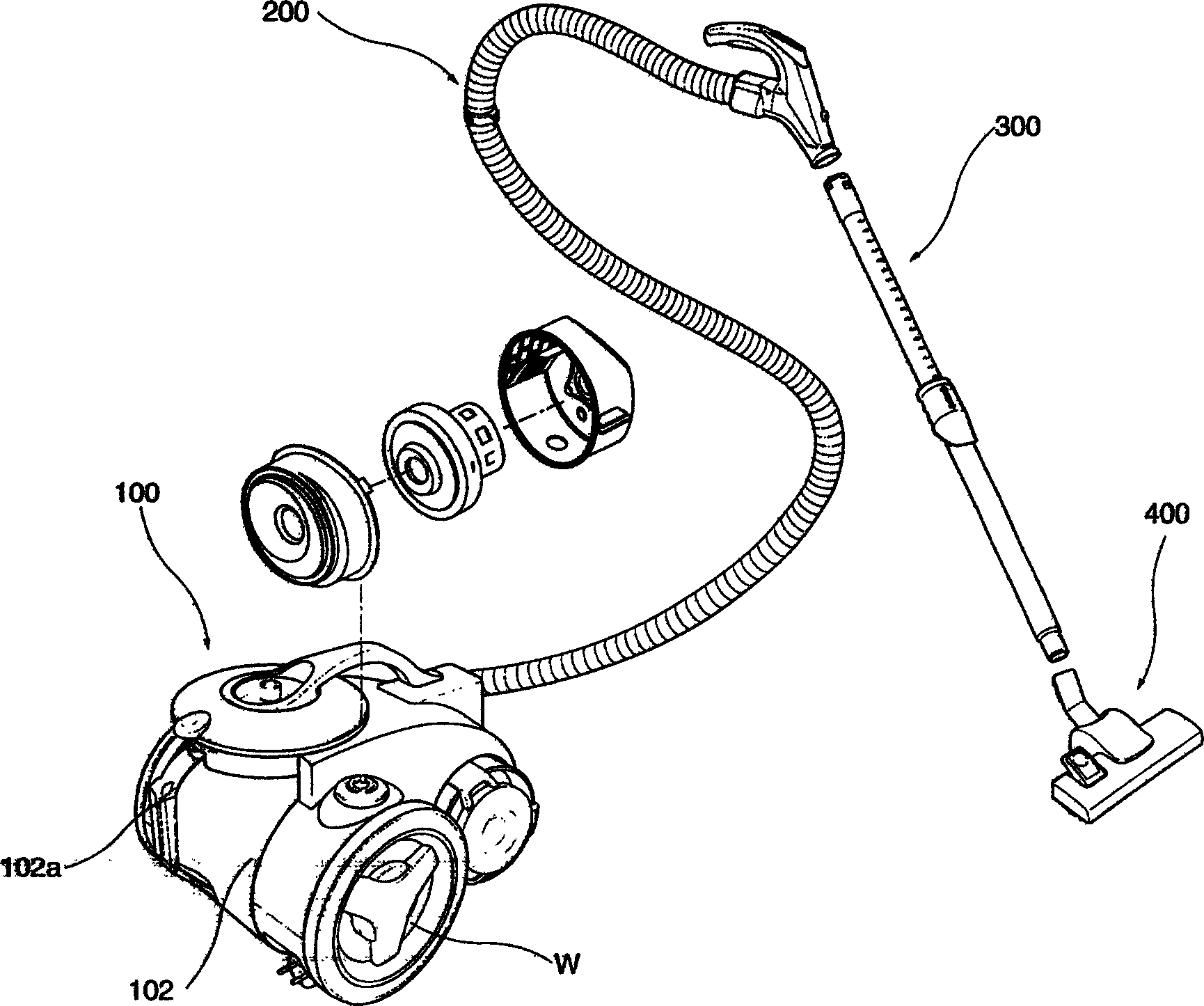
[0025] Such as figure 2 As shown, the vacuum cleaner adopting the noise reduction structure of the vacuum cleaner of the present invention includes: a main body 100, an extension pipe 300, an air suction pipe 200 and a suction nozzle 400; the inside of the main body 100 is provided with a fan motor M (not shown in the figure) output), the fan motor M is used to generate suction, and the dust and foreign objects are sucked into the main body 100 through the suction pipe 200, the extension pipe 300 and the suction nozzle 400.

[0026] The two sides of the rear part of the body 100 are respectively provided with a wheel W, the wheel W is designed to be half the size of the body 100, therefore, the position can be moved freely without being affected by the shape of the floor to be cleaned, and the rim of the wheel W covers There is a non-slip layer made of rubber or urethane material.

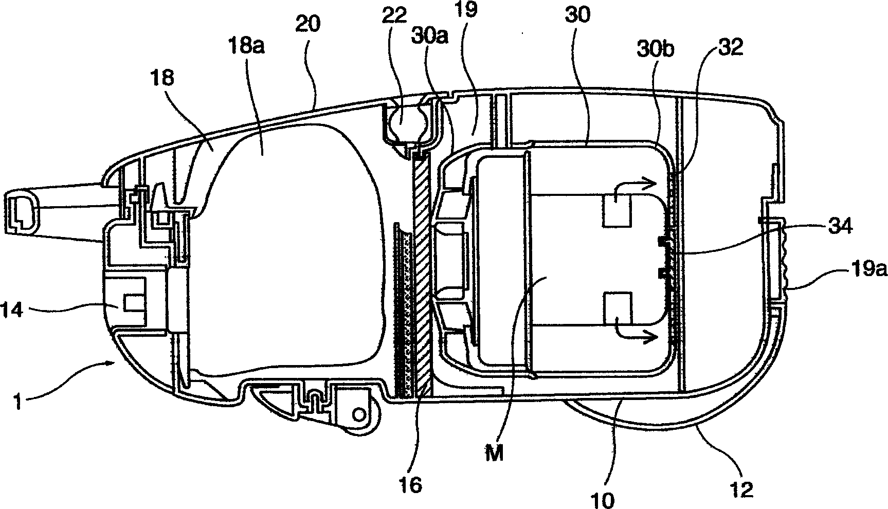
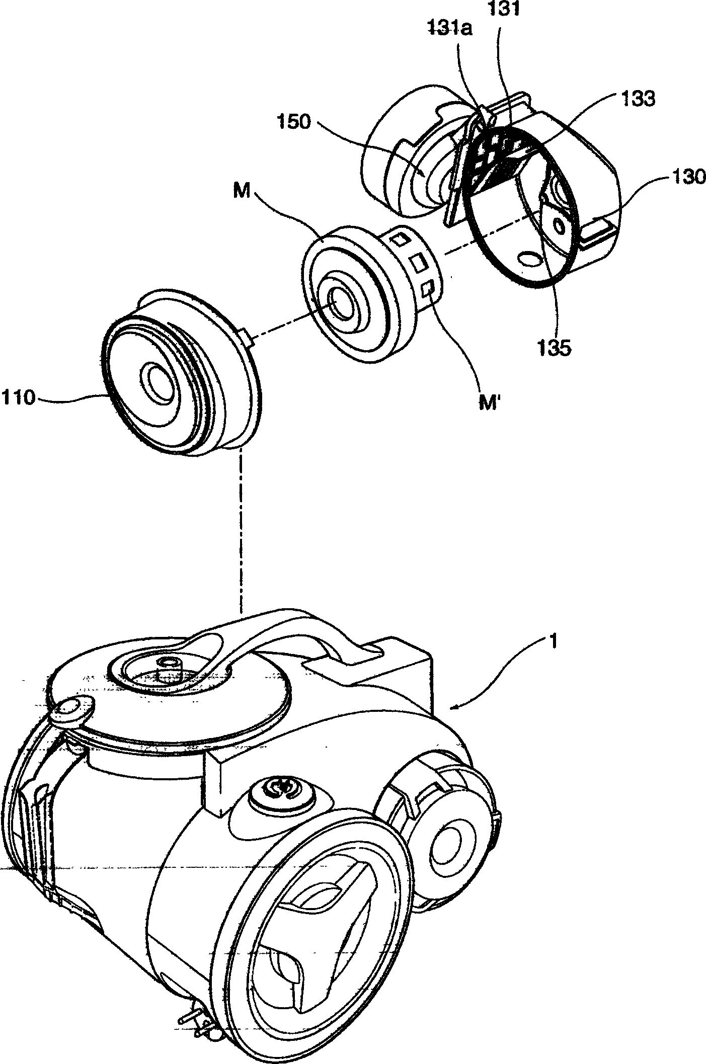
[0027] The rear part of the main body 100 is provided with a dust collecting device 102, the ...

Embodiment approach 2

[0039] More than one guide rib 133 is provided on the inner side of the rear housing 130; a damping pad made of cloth or sponge is provided between the fan motor M and the rear housing 130; other structures and implementations Method 1 is the same. The noise reduction effect of this embodiment is more remarkable.


PUM


Abstract

A noise-reducing structure of vacuum cleaner is composed of the front casing for the front part of fan / motor unit, the back casing for the back part of fan / motor unit, and exhaust unit with filter. Said back casing has a through hole and several guide ribs playing the role of obstacle to make said through hole be opened partly. Its exhaust channel is elongated for attenuating the noise.

Description

technical field [0001] The invention relates to a vacuum cleaner, in particular to a noise reduction structure of the vacuum cleaner. Background technique [0002] A vacuum cleaner is a household appliance used to clean rooms or objects. Its working principle is: through the internal fan motor to generate strong suction, the dust and foreign objects on the floor or in the crevices are sucked into the vacuum cleaner together with the air, and filtered Then the air is discharged, and the dust and foreign matter are collected in the dust collection device. [0003] Such as figure 1 As shown, the existing ordinary vacuum cleaner 1 is formed by a base plate 10 arranged at the bottom and a shell 20 correspondingly connected with the upper part of the base plate 10 to form the appearance of the vacuum cleaner; the two sides of the rear part of the base plate 10 are respectively provided with a wheel 12 , so as to move the position of the vacuum cleaner; the front part of the hous...

Claims


Application Information

Patent Timeline
Patent Type & Authority Applications(China)
IPC IPC(8): A47L9/00
Inventor 李永哲
Owner LG ELECTRONICS (TIANJIN) APPLIANCES CO LTD
Why Eureka
Try Eureka