Dynamo of vacuum duster having brush

A technology for vacuum cleaners and electric brushes, which is applied in the direction of vacuum cleaners, electrical components, electromechanical devices, etc., which can solve the problems of increased number of assembly processes, impact of brushes 131, increased noise, etc., so as to reduce the number of assembly processes and prevent loosening And/or falling off, the effect of reducing the number of parts

Inactive Publication Date: 2005-03-30
LG ELECTRONICS (TIANJIN) APPLIANCES CO LTD
View PDF0 Cites 1 Cited by
  • Summary
  • Abstract
  • Description
  • Claims
  • Application Information

AI Technical Summary

Problems solved by technology

[0006] But, for the above-mentioned existing vacuum cleaner motor with electric brushes, since screw holes 135 need to be formed on the bracket 134, screw connection parts 113 need to be formed on the machine cover 111, and it is necessary to utilize fixing screws 139 to connect the motor to the motor. The brush 131 is connected to the hood 131, so there is a problem that the number of parts and the assembly process will increase.
[0007] In addition, for the conventional vacuum cleaner motor equipped with brushes as described above, since the carbon rod 132 and the commutator 125 maintain elastic contact with each other, and the vacuum cleaner motor needs to rotate at a high speed, there will be the following problems, that is, : The vibration generated during rotation will easily cause the fixing screw 139 to loosen, and thus the brush 131 will hit the machine cover 111, thereby increasing the noise

Method used


Image

  • Dynamo of vacuum duster having brush
  • Dynamo of vacuum duster having brush
  • Dynamo of vacuum duster having brush

Examples


Embodiment Construction

[0026] The present invention will be described in detail below with reference to the accompanying drawings.

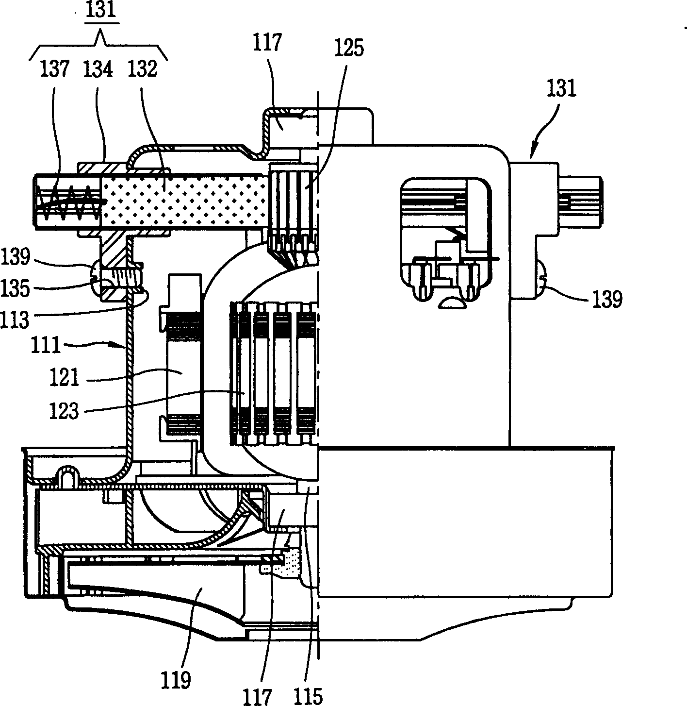
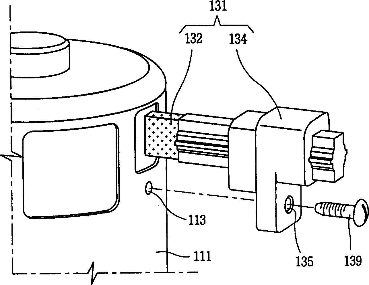
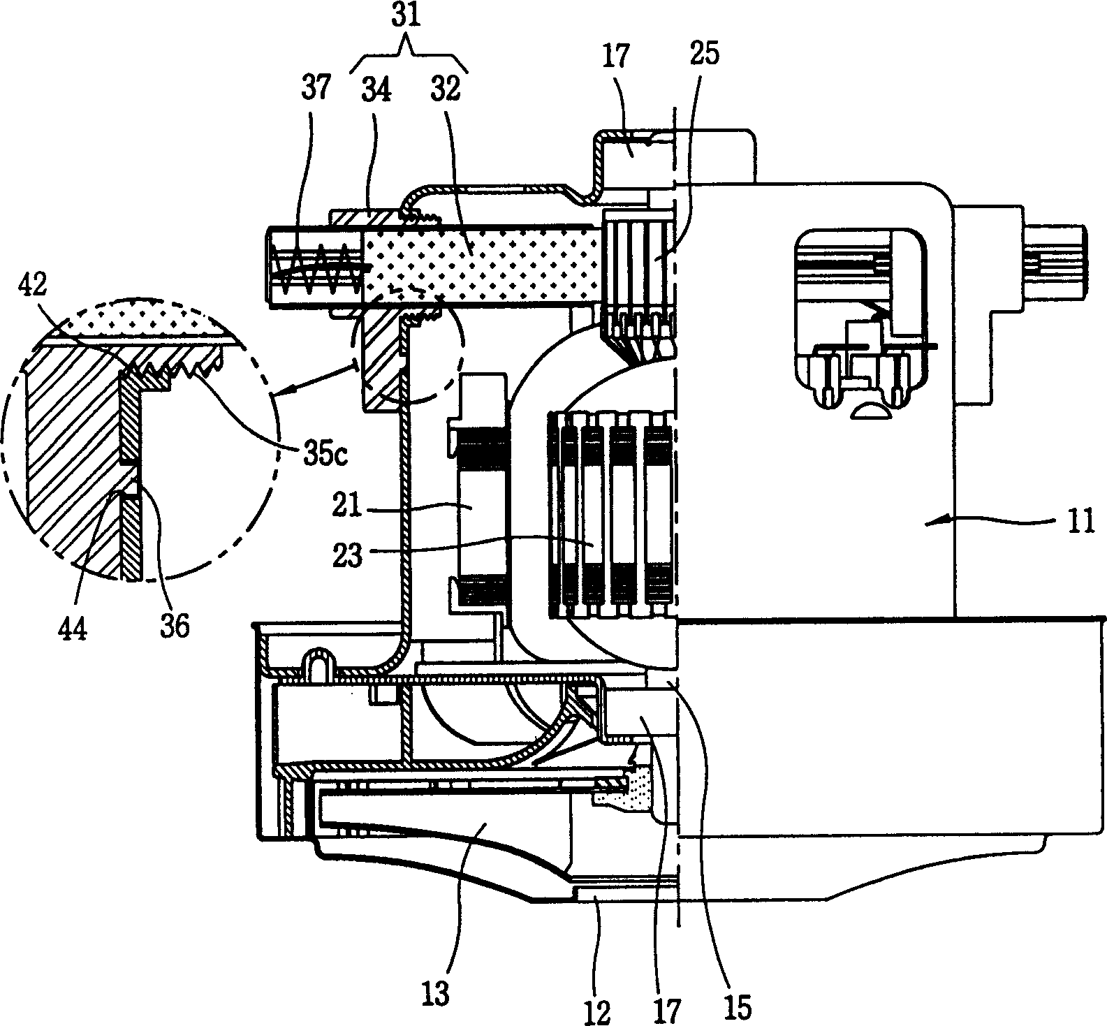
[0027] image 3 It is a half-sectional view of a brush-equipped vacuum cleaner motor employing an example of the present invention, Figure 4 for image 3 An exploded side view of the brush section, Figure 5 for along Figure 4 An enlarged cross-sectional view of the V-V line. As shown in the figure, the vacuum cleaner motor equipped with brushes of the present invention comprises the following structures, that is, a housing 11, which forms an accommodation space inside; a rotating shaft 15, which is installed in the inside of the above-mentioned housing 11 and can rotate; A sub 25 is connected to one side of the above-mentioned rotating shaft 15, and can rotate together with the above-mentioned rotating shaft 15; a brush 31 with a carbon rod 32 and a bracket 34, wherein one end of the above-mentioned carbon rod is in contact with the above-mentioned commutator 25...


PUM


Abstract

The disclosed motor includes following parts: housing cap forming a accommodating space; rotation axis installed inside housing cap; collector connected to one end of the rotation axis is rotated together with the said rotation axis; brush possesses carbon rod and bracket, and the carbon rod along radius direction is setup on outer ring of the collector, and the bracket is connected to the housing cap; the carbon rod is installed inside the bracket, thus, the bracket provides support to the carbon rod, and the carbon rod is able to make relative motion; nut for guiding the carbon rod from outside housing cap to inside housing cap; bolt is connected to nut. Features are fewer parts and fewer numbers of assembling procedures.

Description

technical field [0001] The present invention relates to a vacuum cleaner motor with brushes (MOTOR WITH BRUSH FORVACUUM CLEANER), and more specifically, to a vacuum cleaner motor with brushes capable of reducing the number of parts and assembling processes. Background technique [0002] figure 1 It is a half-sectional view of a conventional vacuum cleaner motor equipped with brushes, figure 2 for figure 1 An exploded side view of the brush section. As shown in the figure, the vacuum cleaner motor equipped with brushes has the following components, namely: a hood 111 with a housing space formed inside; a rotating shaft 115 installed in the inside of the hood 111 and rotatable; The stator 121; the rotor 123 installed inside the stator 121 and rotatable. [0003] In order to be able to accommodate the impeller (impeller) used to generate suction force, one side of the machine cover 111 is expanded outwards, and the center of the machine cover 111 is equipped with a rotatin...

Claims


Application Information

Patent Timeline
Patent Type & Authority Applications(China)
IPC IPC(8): A47L9/00H02K5/14
Inventor 崔奉焉
Owner LG ELECTRONICS (TIANJIN) APPLIANCES CO LTD
Why Eureka
Try Eureka