Paddle type mixing machine

A mixer and paddle technology, applied in mixers, mixers with rotary stirring devices, dissolution and other directions, can solve the problem of affecting the mixing speed and mixing accuracy of the mixer, the effect of convection mixing and shear mixing is small, and there is no obvious effect. Improve and other issues, to achieve the effect of good promotion and application value, low cost, novel and reasonable structure

Inactive Publication Date: 2005-04-27
JIANGSU MUYANG GRP CO LTD
View PDF0 Cites 15 Cited by
  • Summary
  • Abstract
  • Description
  • Claims
  • Application Information

AI Technical Summary

Problems solved by technology

Under the action of the paddles and the materials in its vicinity, they form a shear plane with each other, and the agglomerates or particles of the materials slide and collide with each other, and the shear force received during mixing is large, forming shear mixing; at the same time, the materials are in the Driven by the blade surface of the blade, the blade surface turns to the other direction to form convective mixing; in the above-mentioned area, there is also diffusion mixing between the materials; therefore, the material flows rapidly on the blade and its surrounding area, forming a mixed The material fast flow area in the machine; the materials near the shaft and its vicinity rely on the friction generated between the rotation of the shaft and the material and the drive of the material by the rotation of the support rod. The material flow is mainly affected by convective mixing and diffusion mixing. , and there is no action of the paddle on the material in this section, and the convective mixing and shear mixing are relatively small; therefore, the material flows slowly, forming a slow flow area, which affects the mixing speed and mixing accuracy of the mixer.
In order to improve the working efficiency and quality of the mixer, scientific research departments and production enterprises have carried out a lot of research and development. However, there is a lack of research on the mixing force of the mixer to speed up the mixing of materials in the slow flow area, resulting in the paddle mixer stirring the mixture. The quality and efficiency of raw materials have not improved significantly over the years

Method used


Image

  • Paddle type mixing machine
  • Paddle type mixing machine
  • Paddle type mixing machine

Examples


Embodiment 1

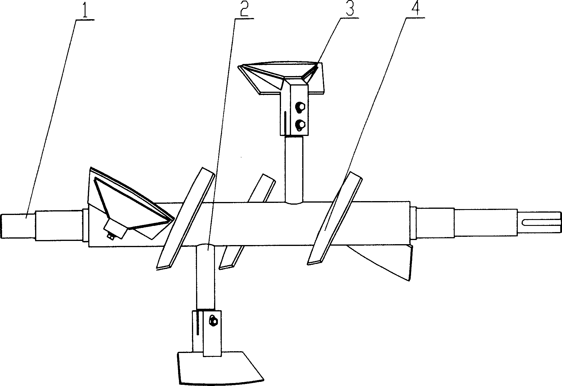
[0015] Embodiment 1: A mixing drum is installed on the machine body, a rotating shaft 1 is installed in the mixing drum, a strut 2 is installed on the rotating shaft 1 , and a paddle 3 is installed on the strut 2 . The auxiliary blade 4 is welded on the rotating shaft between the two struts 2 on the rotating shaft, and the axial distance between the auxiliary blade 4 and the two struts 2 is equal.

Embodiment 2

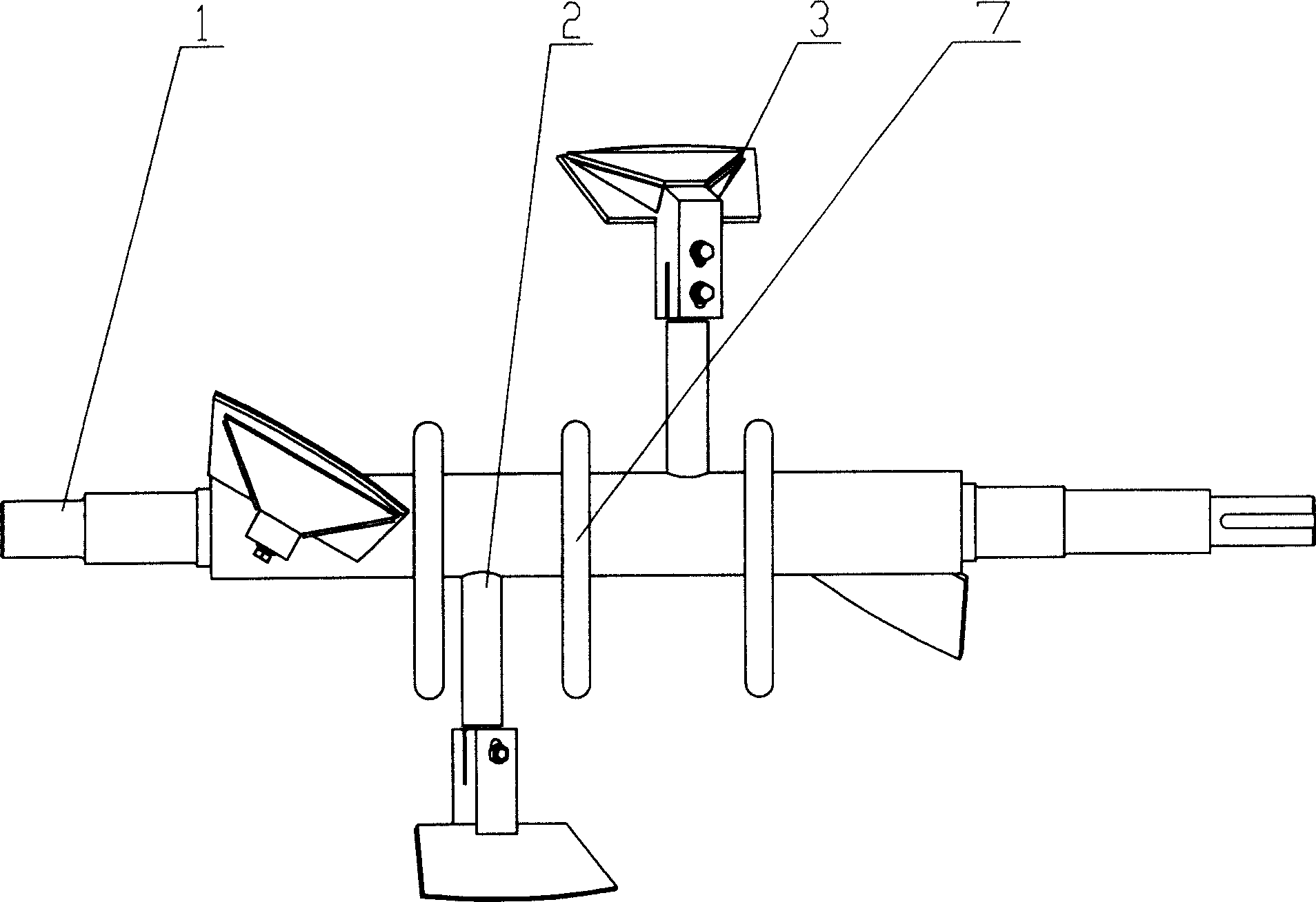
[0016] Embodiment 2: Install a mixing drum on the body, install a rotating shaft 1 in the mixing drum, install a strut 2 on the rotating shaft 1, and install a paddle 3 at the end of the strut. The stirring ring 7 is welded on the rotating shaft between the two struts 2 on the rotating shaft, and the axial distance between the stirring ring 7 and the two struts 2 is equal.

Embodiment 3

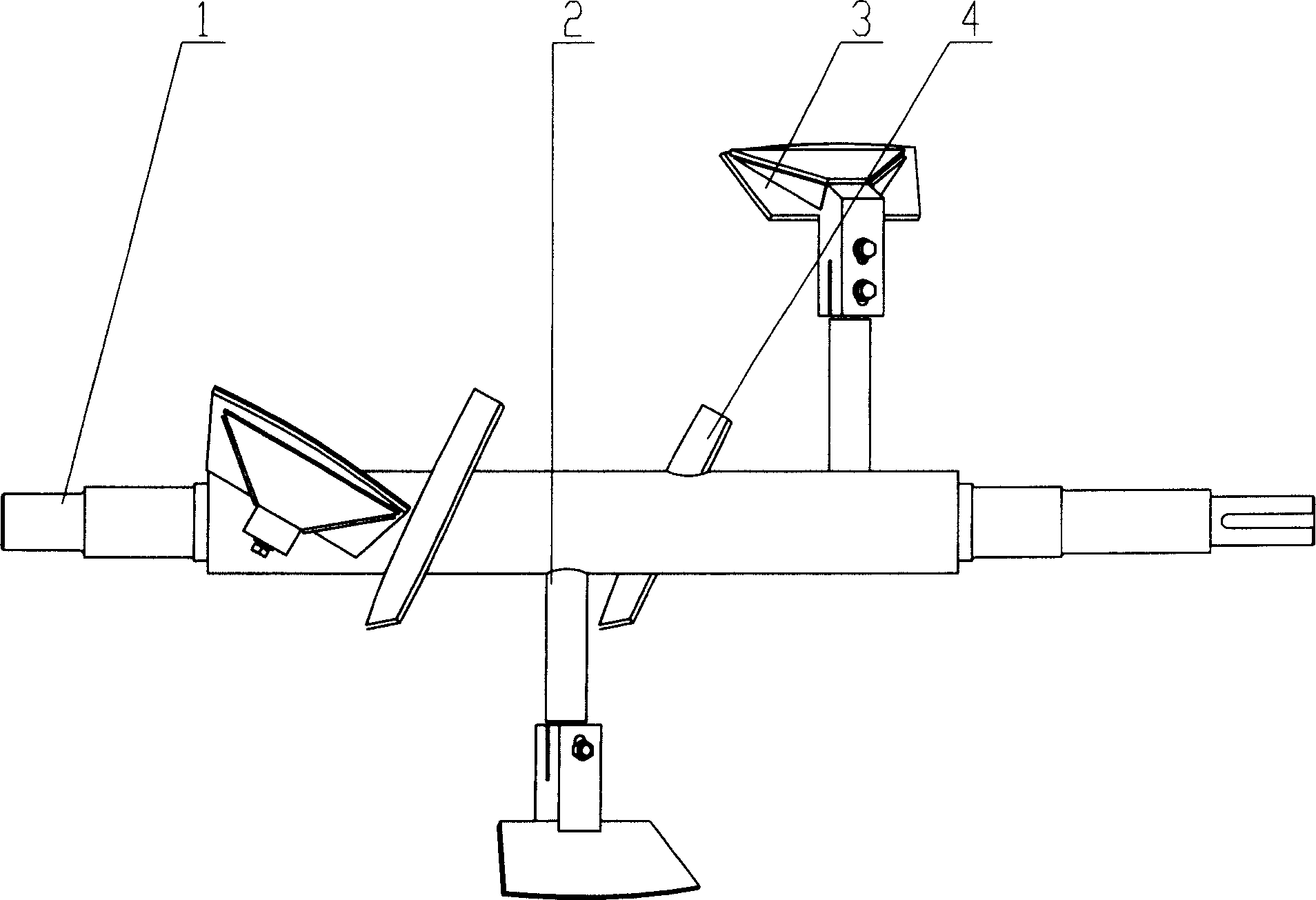
[0017] Embodiment 3: A mixing drum is installed on the machine body, a rotating shaft 1 is installed in the mixing drum, a strut 2 is installed on the rotating shaft 1, and paddles 3 are installed at the ends of the strut 2 . The auxiliary paddle 4 is installed by bolts in the middle section of the strut 2, and the direction of the auxiliary blade 4 can be adjusted by installing the bolts. The installation direction of the auxiliary blade is at a certain angle or opposite to that of the blade at the same pole end.


PUM


Abstract

The present invention discloses one kind of paddle type mixing machine in the field of mixing machinery. There are machine body; stirring barrel set on the machine body; rotor comprising rotating shaft inside the stirring barrel, brace bar on the shaft and paddles fixed in the fast flow area; and characterized transition area stirring part set on the shaft and in the slow flow area. The transition area stirring part may be installed directly on the rotating shaft, on the middle section of the brace bar, or on the support column on the rotating shaft. The present invention has novel structure, simple manufacture process and low cost, and is suitable for both single shaft paddle mixing machine and double shaft paddle mixing machine.

Description

technical field [0001] The invention relates to a paddle mixer and belongs to the technical field of mixers. Background technique [0002] The existing paddle mixer comprises a body, a mixing drum arranged on the body, and a rotating shaft arranged in the mixing drum, on which paddles are installed through struts to form a rotor. One end (tail end) of the strut is fixedly connected to the rotating shaft, and the tail end of the strut extends out of the rotating shaft, and the other end of the strut is connected to the blade by bolts, and the installation angle of the blade on the rotating shaft is at a certain angle relative to the axial center of the rotating shaft. When this kind of mixer is working, the flow speed of the mixing material in the mixing drum is different, and there is a fast flow area and a slow flow area. Under the action of the paddles and the materials in its vicinity, they form a shear plane with each other, and the agglomerates or particles of the mate...

Claims


Application Information

Patent Timeline
Patent Type & Authority Applications(China)
IPC IPC(8): B01F7/18
Inventor 王东范文海冯秋兰
Owner JIANGSU MUYANG GRP CO LTD
Why Eureka
Try Eureka