Rolling stock rail vibration energy piezoelectric power generating method and system thereof

A vibration energy, piezoelectric power generation technology, used in rails, piezoelectric/electrostrictive/magnetostrictive devices, vehicle components, etc. Effect

Inactive Publication Date: 2005-04-27
XI AN JIAOTONG UNIV
View PDF2 Cites 40 Cited by
  • Summary
  • Abstract
  • Description
  • Claims
  • Application Information

AI Technical Summary

Problems solved by technology

Mechanical systems are prone to wear and tear from the pressure d

Method used


Image

  • Rolling stock rail vibration energy piezoelectric power generating method and system thereof
  • Rolling stock rail vibration energy piezoelectric power generating method and system thereof
  • Rolling stock rail vibration energy piezoelectric power generating method and system thereof

Examples


Embodiment Construction

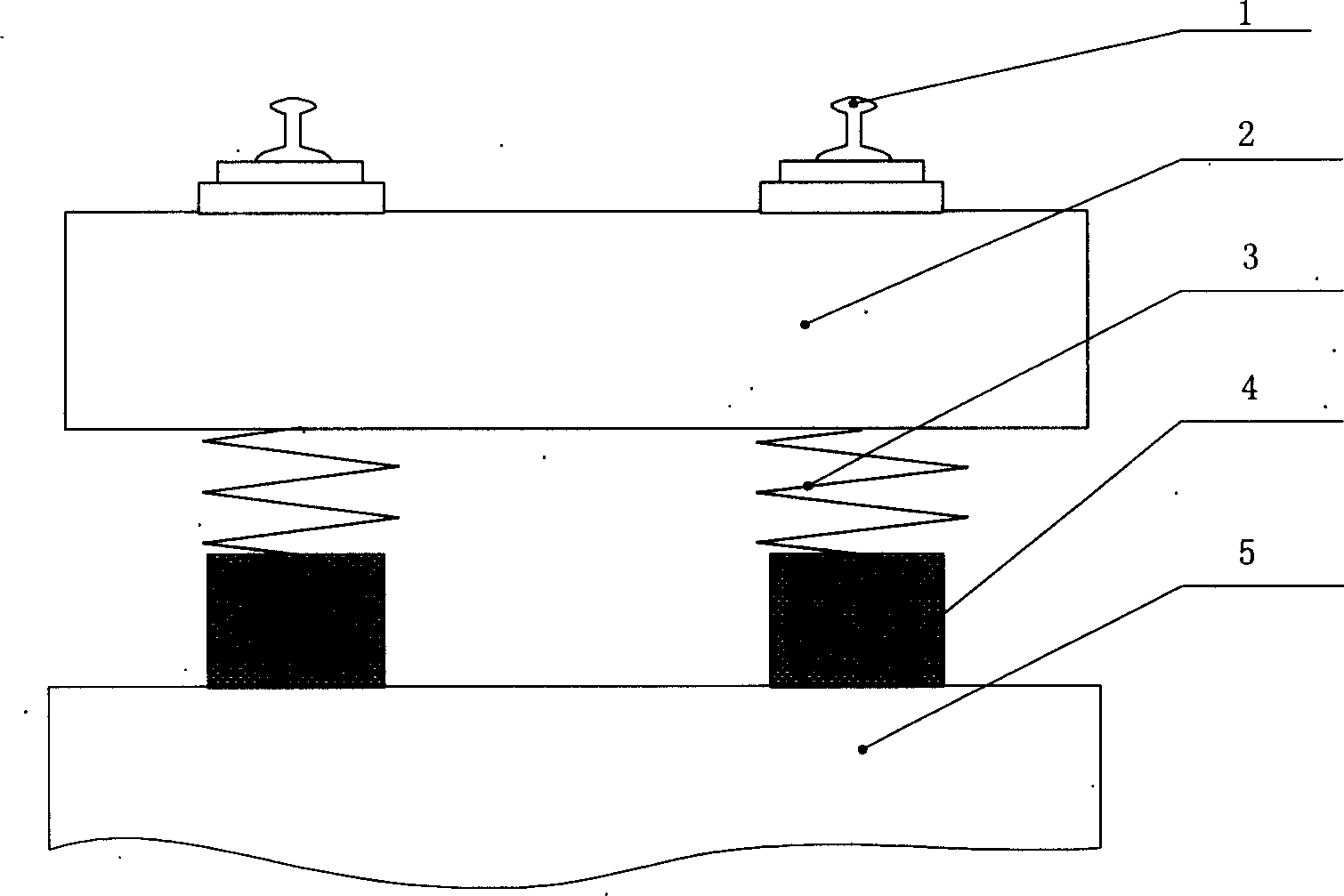
[0059] see Figure 1-7 , according to the technical solution of the present invention, the technical route of the first embodiment is: for the steel spring supporting floating slab track, a piezoelectric device is inserted under the supporting steel spring of the floating slab, and the device is connected in series with the spring, such as figure 2 shown. figure 2 The layers from top to bottom are steel rail 1, floating plate 2, steel spring 3, piezoelectric device 4 and roadbed 5.

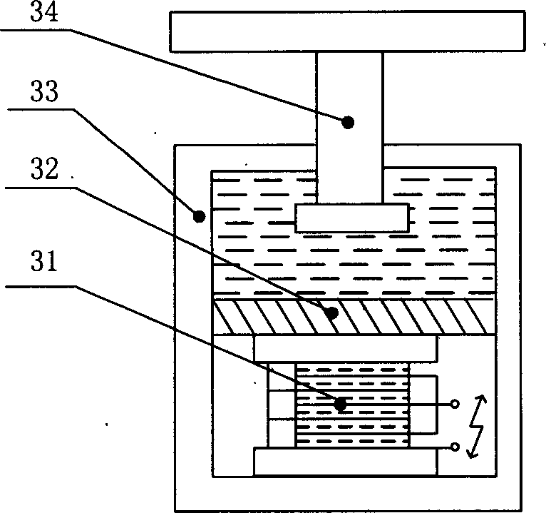
[0060] image 3 The structure of the piezoelectric device in the first embodiment is given. The device consists of an outer piston 34 , an inner piston 32 , a hydraulic cylinder 33 and a piezoelectric stack 31 . The outer piston 34 and the hydraulic cylinder 33 are directly affected by the vibration of the rail vehicle, and the outer piston 34 moves relative to the hydraulic cylinder 33 to generate a pressure change, which is transmitted to the inner piston 32 through the oil pressure. Due t...


PUM


Abstract

The present invention discloses piezoelectric electricity generating method and system utilizing vibration energy of vehicle track. Piezoelectric device is set in the vibration reducing layer of track, so that the vibration energy is utilized to generate electricity for storage and use. The piezoelectric electricity generating system includes at least one piezoelectric device set in the vibration reducing layer of track to convert the vibration energy into electric energy; one electric converter to regulate and convert the generated electric energy for accumulation or driving load; and one energy accumulator connected together. The present invention utilizes the vibration energy of vehicle track and may produce semi-active vibration reducing and noise lowering effect.

Description

technical field [0001] The invention relates to a method and a system for generating electricity on a vehicle track, in particular to a method and a system for generating piezoelectric energy from vibration energy of a vehicle track. Background technique [0002] Energy sources that can be used to generate electricity typically include wind, hydro, solar, nuclear, and steam. With the ever-increasing demand for energy efficiency and conservation, great efforts are being made to develop new sources of energy that have not been used before. Systems and methods have been developed to utilize the energy that vehicles impart to the road or track by their wheels during travel. [0003] These systems can generally be divided into mechanical systems, pneumatic systems and hydraulic systems. [0004] Typical mechanical systems that use the downward force of a vehicle to generate electricity include gear mechanisms and other moving parts. Mechanical systems are prone to wear and tea...

Claims


Application Information

Patent Timeline
IPC IPC(8): E01F11/00F03G7/08H01L41/113H02J7/00H02M3/10
CPCF03G7/08F05B2220/709E01B26/00E01F11/00H02N2/186
Inventor 曹秉刚左贺王丽张政
Owner XI AN JIAOTONG UNIV
Why Eureka
Try Eureka