
Overflow-proof floor drain

A technology for overflow drains and drains, applied in the field of sewer overflow prevention devices, which can solve the problems of inability to prevent sewage overflow, inconvenient maintenance and disassembly, and large space occupation, and achieve the effects of reducing the prevalence of diseases, occupying a small space, and convenient assembly and disassembly

Inactive Publication Date: 2005-05-04
寿健伟
View PDF0 Cites 9 Cited by
  • Summary
  • Abstract
  • Description
  • Claims
  • Application Information

AI Technical Summary

Problems solved by technology

[0002] With the improvement of people's life, the sewer facilities in the toilets or kitchens of residential buildings are becoming more and more complete, but there is no non-return device in the sewer of the building, which often causes sewage to overflow, which not only causes pollution, but is also difficult to eliminate.
At present, the sewer seals used for sanitary ware, such as wash basins, are all S-shaped structures, which take up a lot of space for installation and use, and are inconvenient for maintenance and disassembly. Although they can play a certain role in deodorization, they are prone to clogging, and once they are clogged, it is difficult to unblock them. , cannot prevent sewage from overflowing, and there is no relevant report on an anti-odor and automatic anti-overflow device in the prior art

Method used


Image

  • Overflow-proof floor drain
  • Overflow-proof floor drain
  • Overflow-proof floor drain

Examples


Embodiment 1

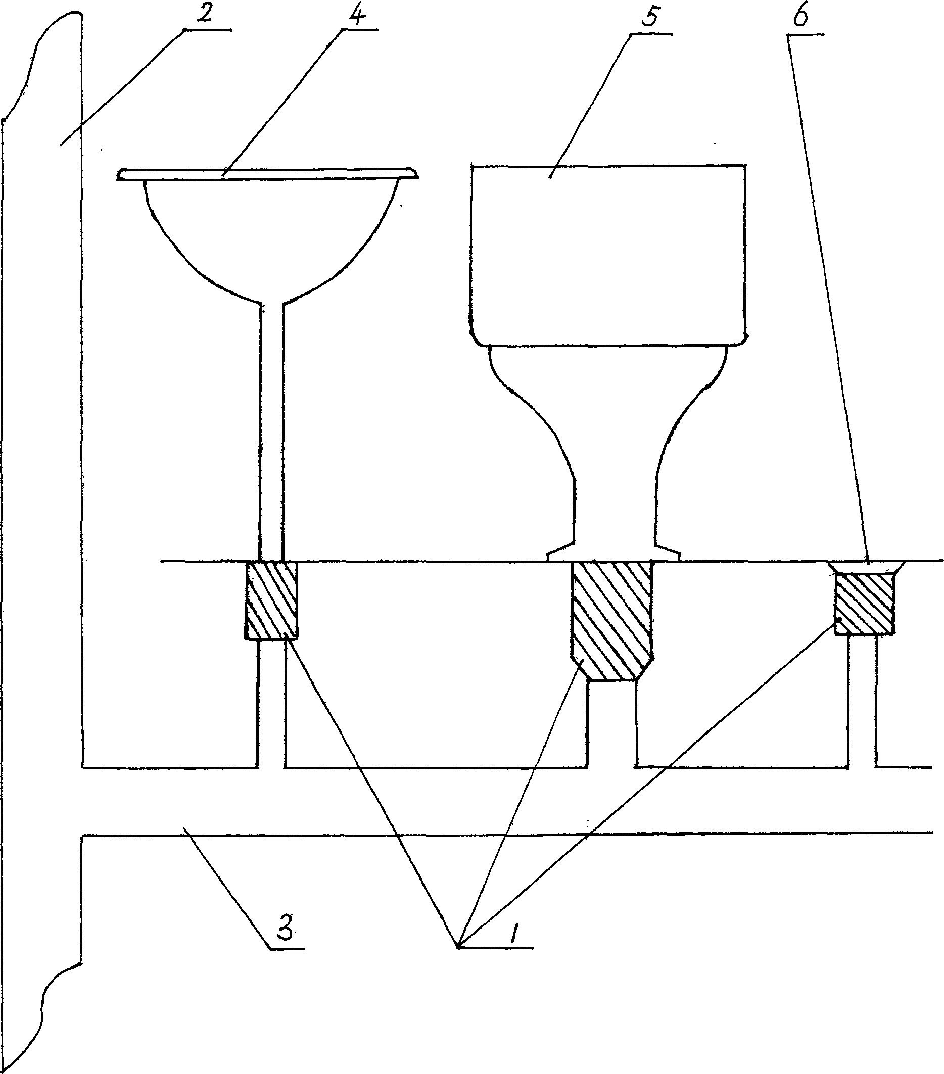
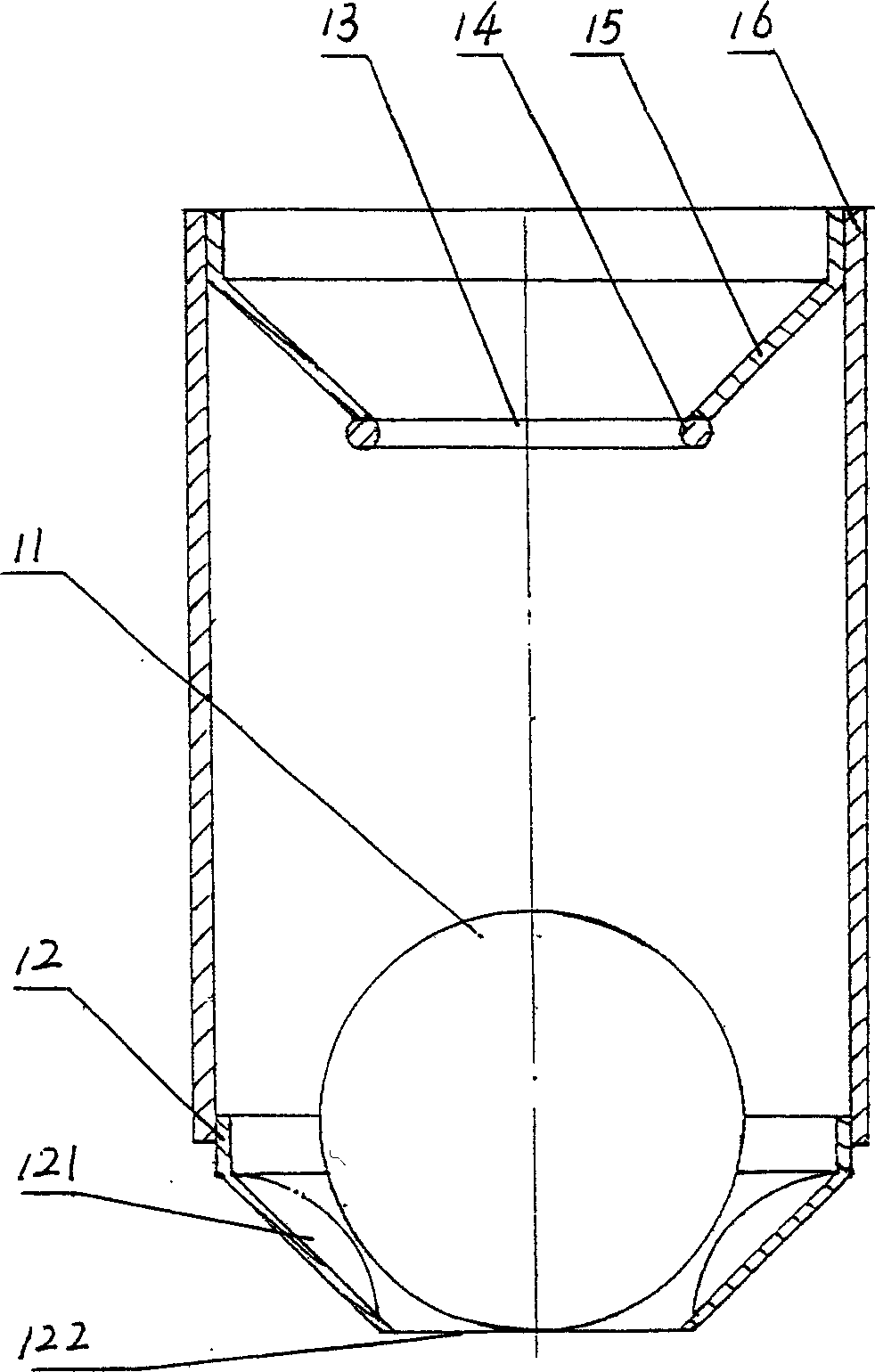
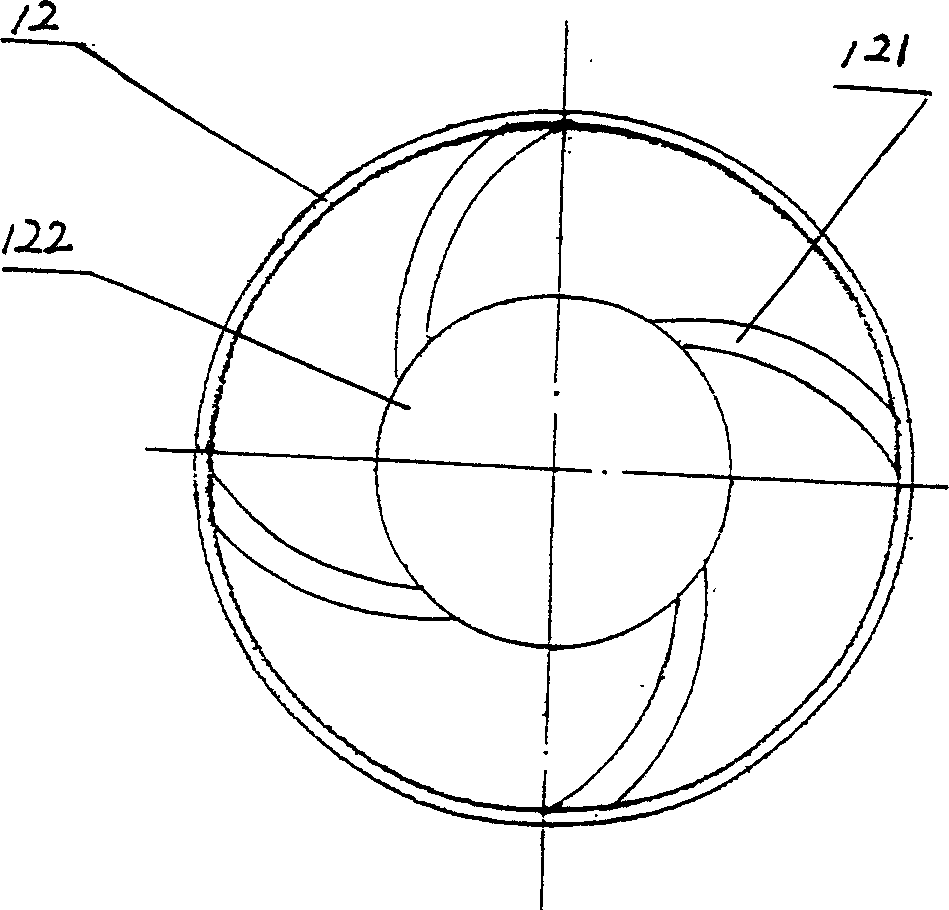
[0025] Such as Figure 1~3 As shown, the present invention is vertically installed between the urinal 5 and the branch sewer 3, including a tubular sewer body 16, a sealing ring 14, a float 11, an inlet pipe 15, an outlet pipe 12, etc., and one end of the sewer body 16 is connected with a Water inlet pipe 15, its other end is connected with water outlet pipe 12, and the water inlet 13 of water inlet pipe 15 retracts inwardly so that water inlet pipe 15 forms a circular truncated structure, and the water inlet 13 of water inlet pipe 15 is connected with sealing ring 14, and the water outlet pipe 12 The water outlet 122 is drawn inward so that the outlet pipe 12 forms a truncated circular structure. The inner surface of the outlet pipe 12 is provided with four evenly distributed swirl tracks 121, and the swirl track turns counterclockwise. In the inner cavity of the device body 16, its diameter is between the diameters of the water inlet and outlet ports 13, 122 and the inner di...

Embodiment 2

[0028] Such as figure 1 , 4, and 5, the present invention is installed vertically between sanitary ware 4 (such as vegetable basin, washbasin and other sanitary ware) and branch sewer 3, including tubular sewer body 16, sealing ring 14, floating ball 11, water inlet pipe 15. Turnback type water outlet pipe 18, one end of the drainer body 16 is connected with a water inlet pipe 15, and the other end is connected with a turnback type water outlet pipe 18, and the water inlet 13 of the water inlet pipe 15 is retracted inwardly so that the water inlet pipe 15 forms a circular truncated structure. The water inlet 13 of the water pipe 15 is connected with a sealing ring 14, and the float 11 is connected with one end of the buoy 17 to form a float in the inner cavity of the drain body 16, and the other end of the buoy 17 is placed in the groove of the return type water outlet pipe 18. There are four evenly distributed inverted V-shaped notches 171 on the side wall of the end, the dia...

Embodiment 3

[0030] As shown in Figure 6, the differences from Example 2 are:

[0031] The gaps on the side walls of the buoy 17 are trapezoidal gaps, and V-shaped sharp feet 19 are formed between the gaps, and the number is 4, evenly distributed.

[0032] In addition, this embodiment can also be used for the floor drain 6, which has dual functions of deodorization and overflow prevention.


PUM


Abstract

This invention is related to an anti-overflowing device of drain, specifically is an automatic anti-flowing device for the sewage. It includes the tube-shaped device body, the sealing ring, and the floating ball. One end of the device body connects with an input pipe, the other end connects with a output pipeline, the infall of the input pipe draws in entad to make the pipe form the round shape, the stoma of the output pipe connects with the sealing ring, the output gate of the output pipe draws in entad to make the pipe form the round shape, on the inner surface of the output pipe is whirling path, the floating ball is set in the lumen of the device body. This invention has simple structure, is easily manufactured, and its cost is low. It takes up small space, the installation is convenient. The construction and maintaining of is easy. It can effectively avoid the pollution caused by the overflowing of the drain and the damage to the furniture and the buildings. It can vertically equipped between the water holding devices (such as washing basin and bedpan) and the drain for anti-overflowing. It can widely used in plants, hotels, schools and the resident houses.

Description

technical field [0001] The invention relates to an anti-overflow device for a sewer, in particular to an anti-overflow sewer device for automatically preventing sewage from overflowing in a sewer. Background technique [0002] Along with the improvement of people's life, the sewer facilities in the bathroom or the kitchen of the resident's house are increasingly complete, but there is no non-return device in the sewer of the building, which often causes the overflow of sewage, which not only causes pollution, but is also difficult to get rid of. At present, the sewer seals used for sanitary ware, such as washbasins, are all S-shaped structures, which take up a lot of space for installation and use, and are inconvenient for maintenance and disassembly. Although they can play a certain role in deodorization, they are prone to clogging, and once they are clogged, it is difficult to unblock them. , can not prevent the sewage from overflowing, and there is no related report that ...

Claims


Application Information

Patent Timeline
IPC IPC(8): E03C1/28E03C1/288E03F3/04E03F7/02
Inventor 寿健伟
Owner 寿健伟
Learn More