

Electronic device
An electronic device and fan technology, which is applied in the direction of program control devices, electrical digital data processing, instruments, etc., can solve the problems of fan noise and seriousness
- Summary
- Abstract
- Description
- Claims
- Application Information
AI Technical Summary
Problems solved by technology
Method used
Image

Examples
Embodiment 1
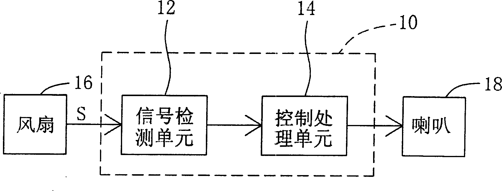
[0012] Please refer to figure 1 , which is a circuit block diagram of the electronic device according to Embodiment 1 of the present invention. exist figure 1 Among them, the electronic device 10 is used in connection with at least one fan 16. When the fan 16 is running, there is noise and at least one signal S is generated. The signal S can be the speed of the fan 16, a pulse or a square wave signal. The electronic device 10 includes a signal detection unit 12 and a control processing unit 14 , the signal detection unit 12 is used for detecting the signal S generated by the fan 16 . The control processing unit 14 makes a judgment according to the signal S, and controls the playing of a piece of music. The electronic device 10 is also connected to a speaker 18 or other sound producing device, and the speaker 18 or other sound producing device is connected with the control processing unit 14 to play the music. It should be noted that the music can be stored in the memory or ...
Embodiment 2
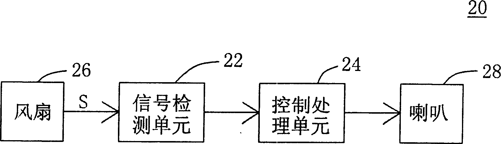
[0016] Please refer to figure 2 , which is a circuit block diagram of the electronic device according to Embodiment 2 of the present invention. exist figure 2 Among them, the electronic device 20 includes at least one fan 26 , a signal detection unit 22 , a control processing unit 24 and a speaker 28 . When the fan 26 is running, there is noise and at least one signal S is generated. The signal S can be the rotation speed of the fan 26 , a pulse or a square wave signal. The signal detection unit 22 is used to detect the signal S generated by the fan 26 , and the control processing unit 24 makes a judgment according to the signal S and controls the playing of a piece of music. Wherein, the loudspeaker 28 or other sounding devices are signal-connected with the control processing unit 24 to play the music. It should be noted that the music can be stored in the memory or hard disk of the electronic device 20 , and the music can also be stored in the storage unit of the contro...
Embodiment 3
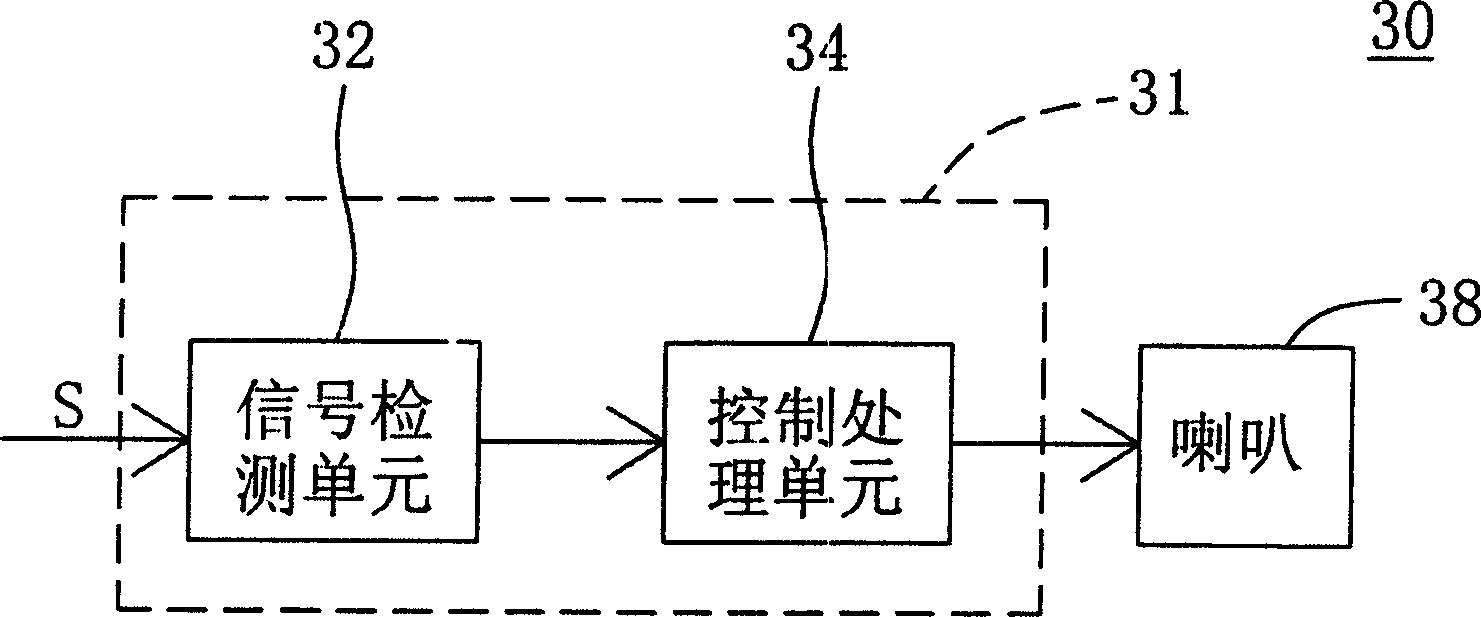
[0020] Please refer to image 3 , which is a circuit block diagram of the fan according to Embodiment 3 of the present invention. exist image 3 When the fan 30 is running, there is noise and at least one signal S is generated, and the signal S can be the rotation speed of the fan 30 , a pulse or a square wave signal. The fan 30 includes a circuit board 31 , a signal detection unit 32 and a control processing unit 34 . The signal detection unit 32 is located on the circuit board 31 for detecting the signal S generated by the fan 30 . The control processing unit 34 is located on the circuit board 31 , and the control processing unit 34 makes a judgment according to the signal S and controls the playing of a piece of music. Wherein, the fan 30 is further connected with a speaker 38 or other sounding device, and the speaker 38 or other sounding device is connected with the control processing unit 34 for playing the music. It should be noted that the music can be stored in the...
PUM
 Abstract
Description
Claims
Application Information