Circuit fault directional detecting and protecting method for power supply system

A line fault and direction detection technology, applied in circuit devices, fault locations, emergency protection circuit devices, etc., can solve the problems of high accuracy requirements of fault models and easy to be affected by interference, and achieve the effect of ensuring protection sensitivity and reliability.

Inactive Publication Date: 2005-05-11
SHANDONG SUNYOUTH ELECTRIC TECH GRP CO LTD
View PDF0 Cites 27 Cited by
  • Summary
  • Abstract
  • Description
  • Claims
  • Application Information

AI Technical Summary

Problems solved by technology

The direction detection speed based on transient signals is relatively high, but the existing detection method—the an

Method used


Image

  • Circuit fault directional detecting and protecting method for power supply system
  • Circuit fault directional detecting and protecting method for power supply system
  • Circuit fault directional detecting and protecting method for power supply system

Examples


Embodiment Construction

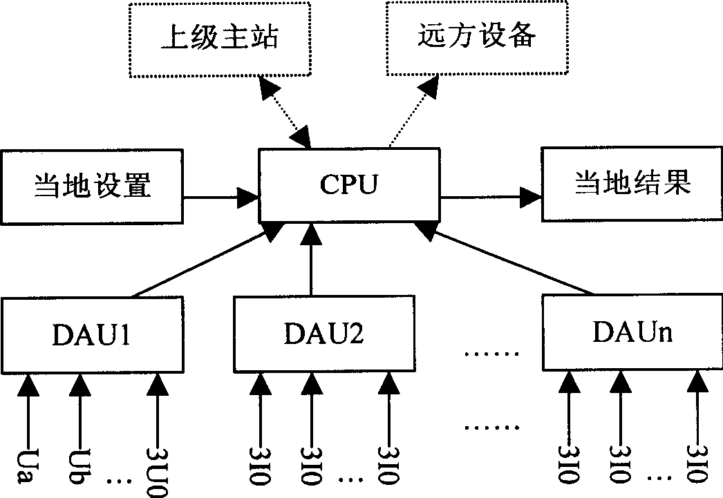
[0026] The power system line fault direction detection and protection method of the present invention can be applied to power grids with different voltage levels to detect different forms of short circuits and grounding faults. It can be implemented in many ways, it can be a protection device with a specific function, or it can share a software and hardware platform with other functions (such as distribution network automation, feeder outlet protection equipment). The following are respectively described:

[0027] 1. Use protective equipment to protect the method

[0028] Using the invention to determine the fault direction only needs the voltage and current signals of the detection point, and does not need fault information of other lines or detection points, and has its own characteristics. The specific implementation steps are as follows:

[0029] 1) Take the change of voltage and current as the start condition of the fault

[0030] For phase-to-phase short-circuit fault...


PUM


Abstract

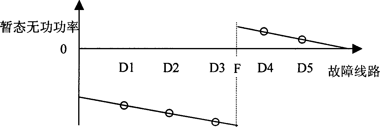
A method for detecting line fault direction judges the fault direction by calculating instant idle power or specific frequency component idle power of transient state voltage current generated by the fault. The fault direction can be detected out quickly within 5 ms and tripping command is followed immediately to separate the fault line out for protection.

Description

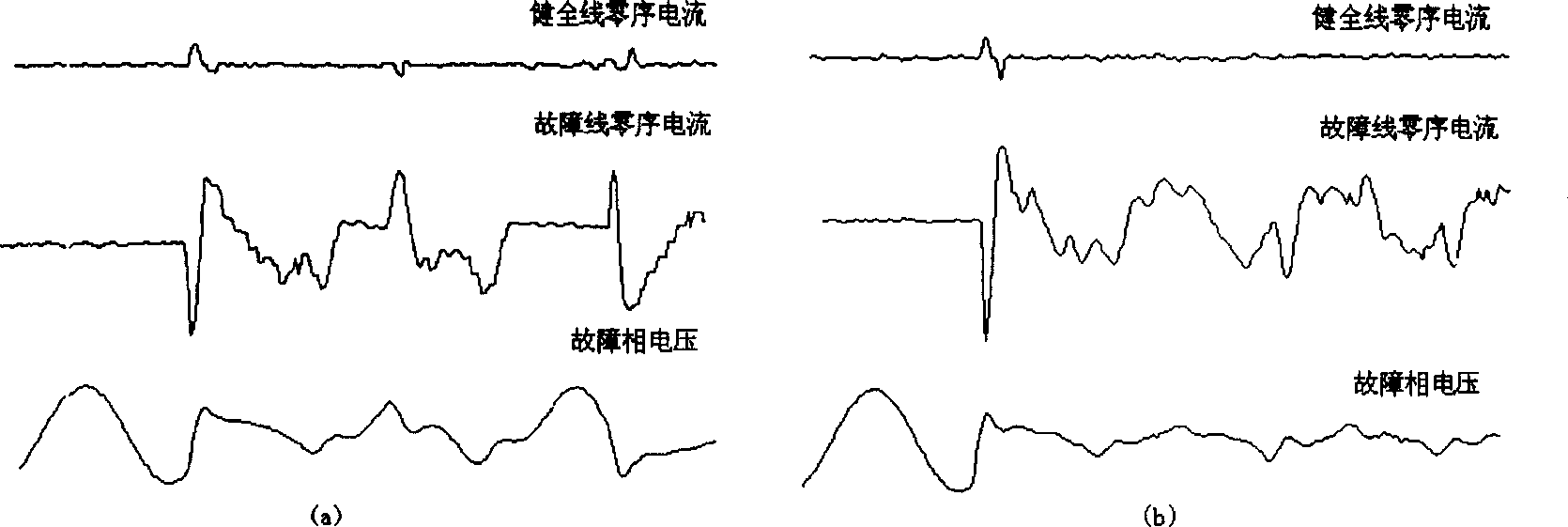
technical field [0001] The invention relates to a method for detecting and protecting a fault direction of a power system line, which belongs to the field of relay protection of a power system, and in particular relates to a method for determining the fault direction by using fault transient state information. Background technique [0002] In power system line fault direction detection methods, for small current grounding faults, the existing detection methods, especially the detection methods based on steady-state information, are not ideal due to weak fault current and unstable arc. The transient current generated by the fault is far greater than the steady-state current, but the direction detection method based on the transient signal—the first half-wave method, the relationship between the transient voltage and current used is established in a short time, and is affected by the line structure, parameters and faults. Influenced by the initial phase angle, etc., the detect...

Claims


Application Information

Patent Timeline
IPC IPC(8): G01R31/08H02H3/00
Inventor 薛永端徐丙垠陈羽李京
Owner SHANDONG SUNYOUTH ELECTRIC TECH GRP CO LTD
Why Eureka
Try Eureka