Small current neutral grounding fault location method based on direction of transient state reactive power

A technology of small current grounding and power direction, applied in the direction of fault location, etc., can solve the problems of inability to detect instantaneous ground faults, reduce detection sensitivity and reliability, and high hardware cost, so as to achieve both protection speed and reliability and ensure protection sensitivity And the effect of reliability and adaptability

Active Publication Date: 2013-08-14
STATE GRID CORP OF CHINA +4
View PDF4 Cites 27 Cited by
  • Summary
  • Abstract
  • Description
  • Claims
  • Application Information

AI Technical Summary

Problems solved by technology

This method has been applied to a certain extent, but it has the following disadvantages: when the grounding resistance is large, the distributed capacitance on the line will shunt the injected signal, reducing the detection sensitivity and reliability; it is necessary to design a dedicated large reactive power signal generator, hardware High cost; and cannot detect momentary ground faults
In the distribution automation system, the master station is used to realize the time synchronization of each detection device, and the time synchronization error is at least a few milliseconds, which cannot be applied to the method of comparing the instantaneous value of the transient zero-sequence current

Method used


Image

  • Small current neutral grounding fault location method based on direction of transient state reactive power
  • Small current neutral grounding fault location method based on direction of transient state reactive power
  • Small current neutral grounding fault location method based on direction of transient state reactive power

Examples


Embodiment Construction

[0028] The small current grounding fault location method of the present invention can be applied to small current grounding faults in power grids of different voltage levels. It can be realized in many ways, it can be a protection device with a specific function, or it can share a software and hardware platform with other functions (such as distribution network automation, feeder outlet protection equipment). Using the invention to determine the fault direction only needs the fault signal at the detection point, and does not need fault information of other lines or detection points, and has its own characteristics. The specific implementation flow chart of this method is as follows: Figure 5 shown. The concrete steps of this method are as follows:

[0029] (1) Take the change of voltage and current as the start condition of the fault

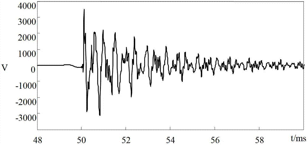
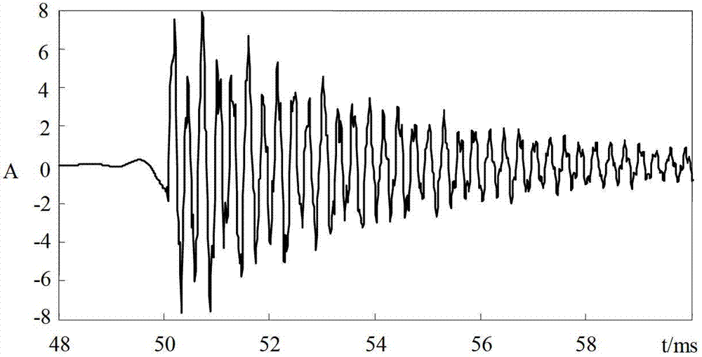
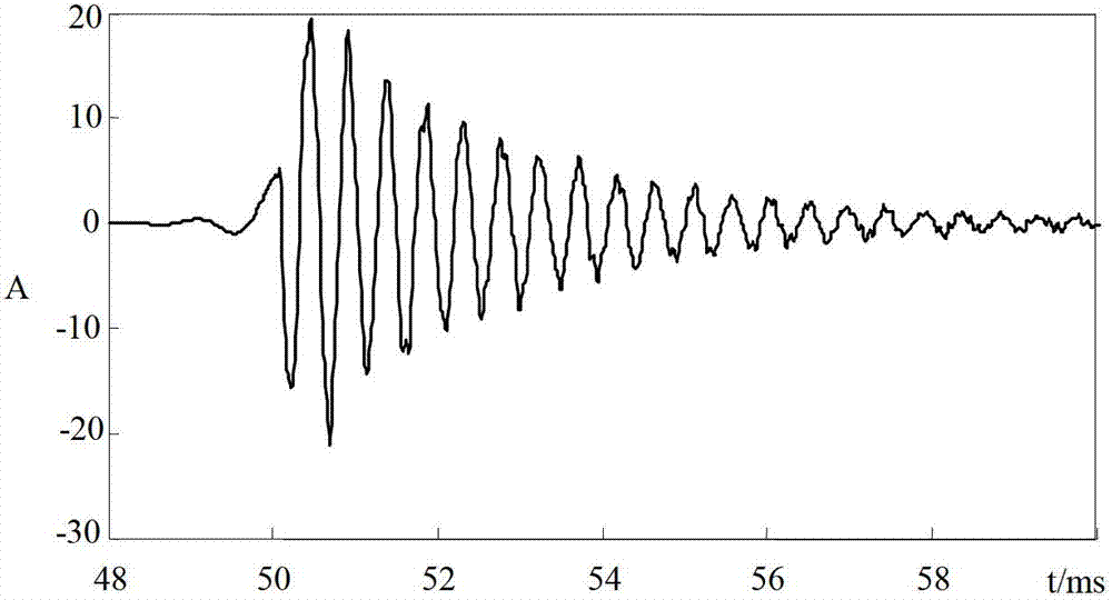
[0030] In the small current grounding system, when a single-phase ground fault occurs, the transient voltage and transient zero-sequence cu...


PUM


Abstract

A small current neutral grounding fault location method based on the direction of transient state reactive power is characterized in that change of voltage or current serves as a failure starting condition, and after the starting, the zero sequence voltage is taken as the participating voltage if a detection point can be used for detecting the zero sequence voltage and if not, the following steps are performed: 1, confirming the fault phase as per characteristics of three transient state line voltages, and 2, confirming the transient state line voltage including the fault message as per the type of the fault phase, taking the transient state line voltage as the participating voltage, confirming the characteristic frequency range, and further building a digital filter to filter the participating voltage and the zero sequence current signal, so as to obtain the component within the characteristic frequency range; and then confirming the direction of the reactive power of all the detection points through utilizing the components of participating voltage and the zero sequence current within the characteristic frequency range, so as to further confirm the fault section. According to the invention, the transient voltage and current signals as well as zero sequence voltage and line voltage are utilized at the same time, the positioning reliability is higher, the adaptability is stronger, quick direction protection for ground fault of all the voltage classes is applicable at the same time, and the protection speed and reliability are taken into consideration.

Description

technical field [0001] The invention relates to a small-current ground fault location method, in particular to a small-current ground fault location method based on the direction of transient reactive power, which is applicable to a single-phase ground fault transient location method of a neutral point non-effectively grounded power grid. Background technique [0002] The distribution network is densely covered in urban, rural and mountainous areas, and is outdoors all year round. It is affected by harsh environments such as wind, rain, frost, lightning, and increasingly severe environmental pollution. Coupled with unpredictable human factors, the probability of failure is high, especially for overhead lines. At present, my country's distribution network mostly adopts the operation mode of ungrounded neutral point and grounded through arc suppression coil. After a ground fault occurs, the faulty line can be selected by using the existing line selection device. However, since ...

Claims


Application Information

Patent Timeline
Patent Type & Authority Applications(China)
IPC IPC(8): G01R31/08
Inventor 李天友李伟新张功林徐丙垠薛永端
Owner STATE GRID CORP OF CHINA
Why Eureka
Try Eureka