Apparatus for the liquefaction of natural gas and methods relating to same
A technology for liquefaction equipment and natural gas, applied in chemical instruments and methods, liquefaction, separation methods, etc., can solve the problems of "dirty", increased cost and complexity of liquefaction equipment or equipment, expensive filtration and purification systems, etc.
- Summary
- Abstract
- Description
- Claims
- Application Information
AI Technical Summary
Problems solved by technology
Method used
Image
Examples
Embodiment Construction
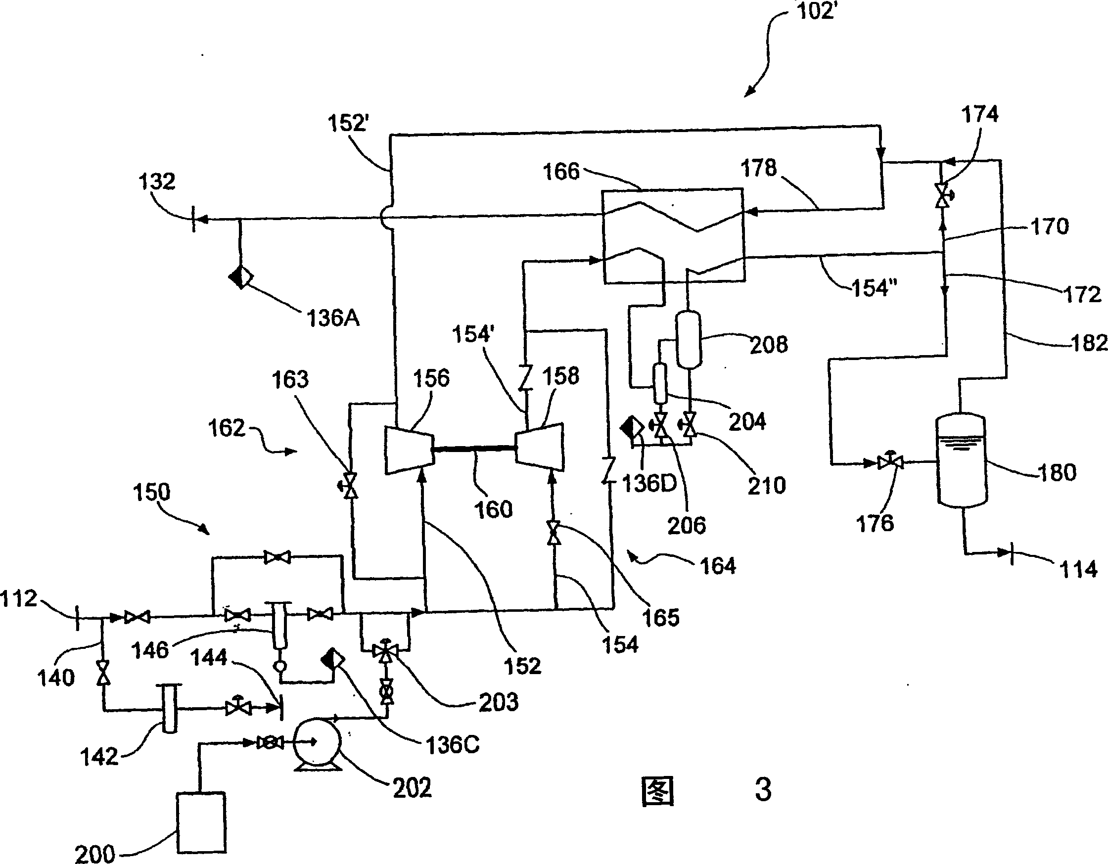
[0133] Referring to Figures 4 and 15, an example of a process performed in the liquefaction unit 102" is illustrated. Note that the attached Figure 14 Is the same process flow diagram as Figure 4 (in combination with the additional components of Figure 3 - such as compressor 154, expander 156, etc.), but with component numbers omitted for clarity. The overall process has been described above with reference to accompanying drawing 4, and the typical conditions of gas / liquid / slurry at various positions in the entire liquefaction plant will be listed below based on the calculated operation design of the liquefaction plant 102", which are referred to as states herein point.
[0134] At state point 400, the gas exits the distribution line and enters the liquefaction unit, the gas state is about 60°F, the pressure is about 440 psia, and the flow rate is about 10,000 lbm / hr.
[0135] Splitting occurs at state points 402 and 404, with approximately 5056 lbm / hr of fluid passing throu...
PUM
 Abstract
Description
Claims
Application Information
 - R&D
- Intellectual Property
- Life Sciences
- Materials
- Tech Scout
- Unparalleled Data Quality
- Higher Quality Content
- 60% Fewer Hallucinations
Browse by: Latest US Patents, China's latest patents, Technical Efficacy Thesaurus, Application Domain, Technology Topic, Popular Technical Reports.
© 2025 PatSnap. All rights reserved.Legal|Privacy policy|Modern Slavery Act Transparency Statement|Sitemap|About US| Contact US: help@patsnap.com


