Supercharge Your Innovation With Domain-Expert AI Agents!

Driving circuit for energy recovery in plasma display panel

A technology for energy recovery and driving circuits, applied in static indicators, irreversible DC power input conversion to AC power output, instruments, etc., can solve the problem of complex circuit control, voltage can not increase input voltage, and difficult to control board capacitance. Sudden changes in terminal voltage, etc.

Inactive Publication Date: 2005-05-11
SEOUL NAT UNIV R&DB FOUND
View PDF0 Cites 5 Cited by
  • Summary
  • Abstract
  • Description
  • Claims
  • Application Information

AI Technical Summary

Problems solved by technology

The disadvantage of the third conventional circuit is that the voltage across the plate capacitance suddenly changes from a positive input voltage to a negative input voltage, as is the case with the second conventional circuit, which cannot be raised to the input voltage due to system losses
However, the disadvantages of the fourth conventional circuit are that the circuit and its control operation are too complicated, and the voltage between the two terminals of each plate capacitor cannot be raised to the input voltage due to system loss
[0010] Disadvantages of the first conventional circuit are the losses due to hard switching and the need for accurate turn-off control of the switches
The disadvantage of the second conventional circuit is that a large capacitance used as another voltage source must be provided outside the circuit, and the number of components increases
In addition, the third conventional circuit has disadvantages in that it is difficult to control a sudden change in voltage between both ends of the panel capacitance, and it is difficult to smoothly supply energy to the panel through the first to fourth switches SW1 to SW4
The disadvantage of the fourth traditional circuit is that the circuit and its control are too complicated, and the board must be divided into two parts and driven
The disadvantage of the second to fourth conventional circuits is that the voltage across the plate capacitance cannot be raised to the input voltage due to system losses
Therefore, the second to fourth conventional circuits have a problem in that they cannot guarantee 100% zero-voltage switching of the inverting clamp switches SW3 and SW4 that supply discharge energy to the board, and cause switching loss and EMI noise

Method used


Image

  • Driving circuit for energy recovery in plasma display panel
  • Driving circuit for energy recovery in plasma display panel
  • Driving circuit for energy recovery in plasma display panel

Examples


Embodiment Construction

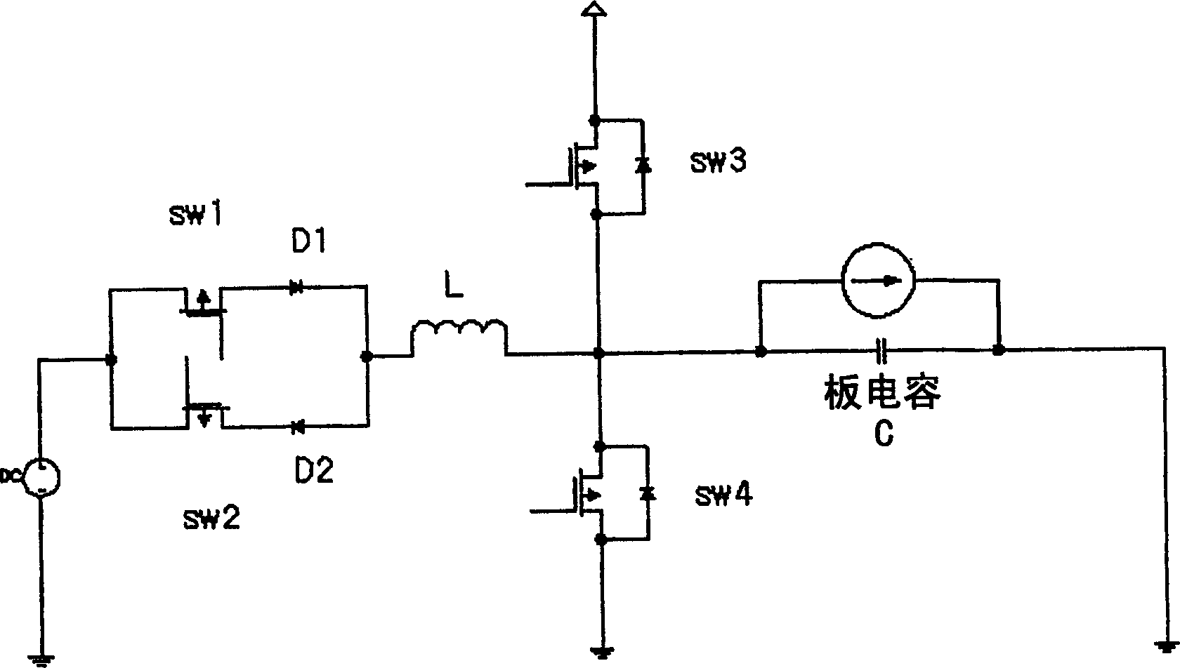
[0044] In the energy recovery driving circuit according to the first embodiment of the present invention, the primary coil is connected between the resonance inductor and the load, the first switching device is connected between the power supply voltage and the resonance inductor, and the second switching device connected between the resonant inductor and ground; and the energy recovery unit further includes first and second diodes for conducting current in the direction of the voltage source. The secondary coil includes: a first secondary coil, connected in series with a first diode between the supply voltage and ground, and coupled to the primary coil so that charging current flows through the voltage source when the charging current flows through the primary coil and a second secondary coil connected in series with the second diode between the supply voltage and ground and coupled to the primary coil so that the discharge current flows into the voltage source when the discha...


PUM


Abstract

The energy recovery driving circuit of the present invention includes a resonant inductor, a primary coil of a transformer, at least one secondary coil, and an energy recovery unit. The resonant inductor is connected to the load so that charging and / or discharging current applied to the load can flow through the resonant inductor. The primary coil is connected to the resonant inductor, and is connected to the resonant inductor and the load such that charging and / or discharging current flows through the primary coil when charging and / or discharging current flows through the load. The secondary coil is coupled to the primary coil. The energy recovery unit generates current according to a predetermined number of turns of the secondary coil to restore the current flowing through the secondary coil to the voltage source.

Description

technical field [0001] The present invention generally relates to a drive circuit for energy recovery in a plasma display panel, and more particularly, to a drive circuit for energy recovery in which a new structure using a regenerative transformer is adopted, thereby simplifying the The energy recovery circuit used during the hold period of the plasma display panel improves energy recovery efficiency and enables zero voltage switching. Background technique [0002] In case of a surface discharge type alternating current (AC) plasma display panel (PDP), a high voltage is periodically applied to the panel capacitance. Generally, a drive circuit for energy recovery is used in a drive circuit of such a PDP. The energy recovery drive circuit is a circuit that improves system efficiency, reduces electromagnetic interference (EMI) noise, and stably / effectively drives the PDP during the hold period by recovering the energy of the charging / discharging board capacitance. [0003] ...

Claims


Application Information

Patent Timeline
Patent Type & Authority Applications(China)
IPC IPC(8): G09G3/20G09G3/28H02M7/48
CPCG09G3/294G09G3/2965G09G2310/066G09G3/296
Inventor 曹普衡李东映
Owner SEOUL NAT UNIV R&DB FOUND
Features
  • R&D
  • Intellectual Property
  • Life Sciences
  • Materials
  • Tech Scout
  • Unparalleled Data Quality
  • Higher Quality Content
  • 60% Fewer Hallucinations
Learn More