Controllable flux permanent magnetic synchronous motor of multiple pole number built-in mixed rotor magnetic path structure

A hybrid and rotor technology, applied in the direction of magnetic circuit shape/style/structure, magnetic circuit rotating parts, etc., can solve the problems of inverter power device damage, loss of magnetic field weakening control ability, decline, etc., and achieve remarkable results

Inactive Publication Date: 2005-05-18
TIANJIN UNIV
View PDF0 Cites 41 Cited by
  • Summary
  • Abstract
  • Description
  • Claims
  • Application Information

AI Technical Summary

Problems solved by technology

In field-weakening speed regulation, if the total stator current is limited, then the quadrature axis current vector i q The resulting torque that can be utilized will decrease; at the same time, due to the direct axis current vector i d To exist all the time, additional copper loss will be generated in the stator three-phase winding
As for the frequency converter, if the inverter fails and the magnetic field weakening control capability is lost, the permanent magnet...

Method used


Image

  • Controllable flux permanent magnetic synchronous motor of multiple pole number built-in mixed rotor magnetic path structure
  • Controllable flux permanent magnetic synchronous motor of multiple pole number built-in mixed rotor magnetic path structure

Examples


Embodiment Construction

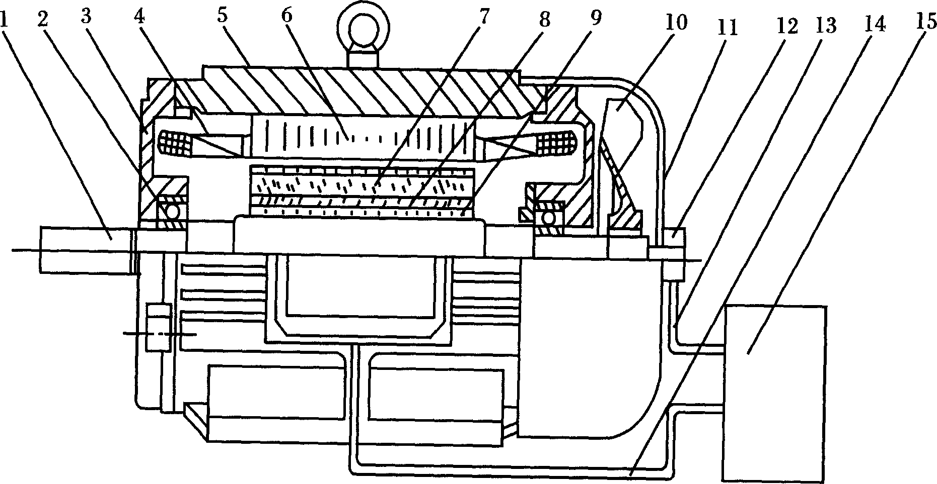
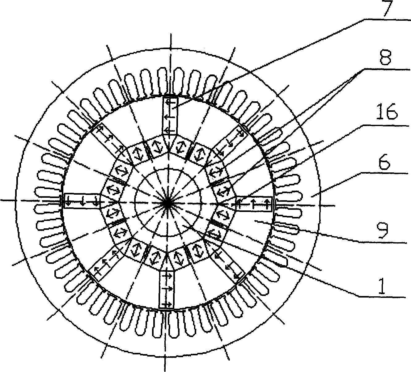
[0010] Specific embodiments of the present invention are described below in conjunction with accompanying drawings, and the whole motor is implemented as follows.

[0011] It has been mentioned above that the multi-pole built-in hybrid rotor magnetic circuit structure controllable flux permanent magnet synchronous motor of the present invention - memory motor, except for the motor rotor, other parts of the motor are basically the same as the traditional permanent magnet synchronous motor. That is to say, the end cover 3 of the motor, the frame 5, the air-conditioning fan 10, the windshield 11, the stator core 6, the winding, insulation, embedding, dipping, drying, and pressing into the frame 5 of the three-phase stator winding 4 The manufacturing process is basically the same as that of the traditional permanent magnet synchronous motor. What needs to be emphasized again is that ① in order to weaken the reluctance torque of the permanent magnet motor, the stator core 6 is made...


PUM


Abstract

This invention provides a multiple integral hybrid rotor magnetic circuit structure controlled flux magnet synchronous motor including motor spindle, a stator winding, a stator iron core, AlNiCo magnet, A Nd FeB magent, a rotor iron core, a position sensor, a sensor cable, a motor cable and a converter. The permanent rotor is in an integral hybrid rotor magnetic circuit structure, the magnet in the rotor iron cover is set in U shape, the NdFeB is placed tangentially and the AlNiCo magnet is in radial position characterizing in being called a memory motor since it can apply an amplitude controlled d-axis current vector to change the magnetization intensity of the rotor magnet and remember the changed flux intensity.

Description

technical field [0001] The invention belongs to motor and electric transmission control, in particular to a permanent magnet synchronous motor with multi-pole number built-in hybrid rotor structure magnetic circuit and magnetic flux controllable. Background technique [0002] Generally, in the design of the rotor magnetic circuit and the size determination of the permanent magnets of traditional permanent magnet synchronous motors, it should be considered that the demagnetization of the permanent magnets should be prevented even under the most extreme working conditions. This means that at the maximum operating temperature, the thickness of the permanent magnets in conventional permanent magnet motors is large enough that the demagnetizing magnetomotive force generated by the armature reaction is lower than the coercive force of the permanent magnets. This is because in traditional permanent magnet motors, especially rare earth permanent magnet...

Claims


Application Information

Patent Timeline
IPC IPC(8): H02K1/27
Inventor 陈益广沈勇环王晓远
Owner TIANJIN UNIV
Why Eureka
Try Eureka