Metal band type stepless speed variator lubricating device

A technology of continuously variable transmissions and lubricating devices, applied in the direction of transmission, transmission parts, gear lubrication/cooling, etc.

Active Publication Date: 2005-05-25
HONDA MOTOR CO LTD
View PDF1 Cites 5 Cited by
  • Summary
  • Abstract
  • Description
  • Claims
  • Application Information

AI Technical Summary

Problems solved by technology

In the past, the lubricating oil flow rate was controlled by the throttle valve installed in the lubricating oil injection hole of the nozzle. However, since the lubricating oil flow rat

Method used


Image

  • Metal band type stepless speed variator lubricating device
  • Metal band type stepless speed variator lubricating device
  • Metal band type stepless speed variator lubricating device

Examples


Embodiment Construction

[0021] Next, embodiments of the present invention will be described based on embodiments of the present invention shown in the drawings.

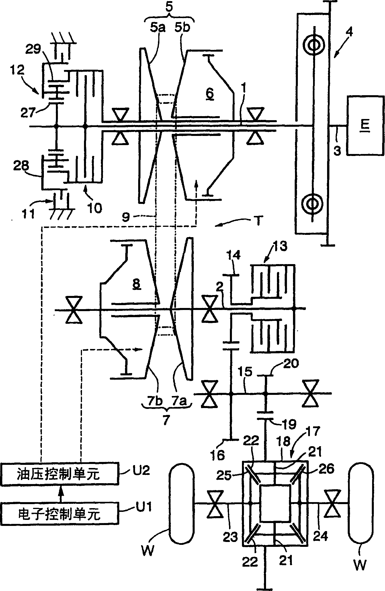
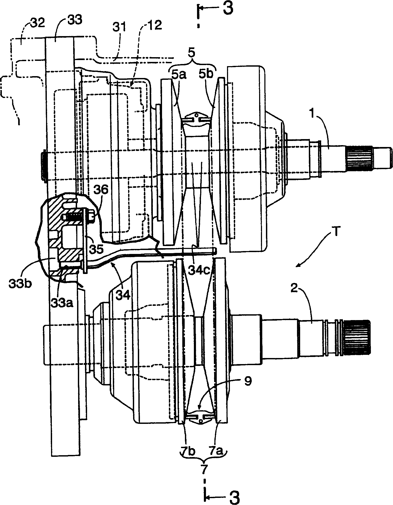
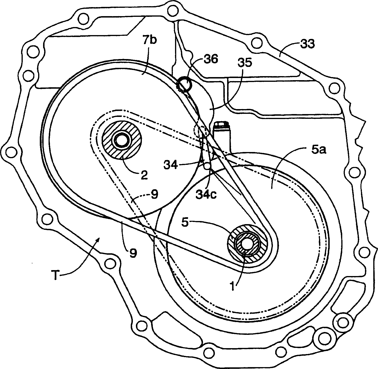
[0022] Figure 1 to Figure 6 represents an embodiment of the invention in which figure 1 It is a schematic diagram of a vehicle power transmission system equipped with a metal belt type continuously variable transmission, figure 2 It is the front view of the main parts of the metal belt continuously variable transmission, image 3 yes figure 2 The 3-3 line profile, Figure 4 It is a perspective view of the main parts of the metal belt continuously variable transmission, Figure 5 yes image 3 Enlarged view of main parts, Image 6 yes Figure 5 6-way view.

[0023] Such as figure 1 As shown, the metal belt continuously variable transmission T for vehicles includes a drive shaft 1 and a driven shaft 2 arranged in parallel, and the left end of the crankshaft 3 of the engine E is connected to the right side of the drive shaft 1 via a...


PUM


Abstract

The invention provides a lubricating device for a metal belt type continuously variable transmission. The device hangs the metal belt on the driving pulley and the driven pulley with variable groove width, and the lubricating oil sprayed by the nozzle (34) acts on the driving belt. The pulley, driven pulley and metal belt are lubricated, wherein: the nozzle (34) has a lubricating oil spray hole (34c) for spraying lubricating oil, and a lubricating oil supply connected to the upstream side of the lubricating oil spray hole (34c) The flow control part (34e) of the passage (34a). Since the flow control part (34e) is provided in addition to the lubricating oil injection hole (34c), the lubricating oil flow rate can be controlled at the desired flow rate while reducing the amount of lubricating oil sprayed from the lubricating oil injection hole (34c). Speed, so that the lubricating oil is sprayed radially to ensure sufficient lubricating effect.

Description

technical field [0001] The present invention relates to a metal belt type continuously variable transmission which winds a metal belt on a driving pulley and a driven pulley, changes the groove width of the two pulleys, and controls the transmission ratio steplessly, especially for these Lubricating device for lubricating driving pulleys, driven pulleys and metal belts. Background technique [0002] Patent Document 1 below describes that, in such a metal belt type continuously variable transmission, lubricating oil is sprayed from a nozzle arranged between the driving pulley and the driven pulley, and the driving pulley, the driven pulley, and the metal belt are Lubricated metal belt continuously variable transmission. [0003] [Patent Document 1] JP-A-60-159468 [0004] However, in order to increase the lubricating effect while suppressing the amount of lubricating oil sprayed from the nozzle, it is desirable to spray the minimum necessary lubricating oil radially and spr...

Claims


Application Information

Patent Timeline
IPC IPC(8): F16H9/12F16H57/04
CPCF16H57/0456F16H57/0489
Inventor 韭泽英夫岩田理孝佐藤和美羽生惠一
Owner HONDA MOTOR CO LTD
Why Eureka
Try Eureka