Reverse pedaling and accelerating mechanism for bicycle

The technology of a speed-increasing mechanism and a bicycle is applied in the direction of vehicle gearbox, vehicle parts, wheel transmission device, etc., which can solve the problems of operation failure and inability to change gears, and achieve the effects of low cost, convenient manufacture and reasonable design.

Inactive Publication Date: 2005-06-01
游志成
View PDF0 Cites 4 Cited by
  • Summary
  • Abstract
  • Description
  • Claims
  • Application Information

AI Technical Summary

Problems solved by technology

Due to the long distance between the operating handle and the shifting part, it is pulled

Method used


Image

  • Reverse pedaling and accelerating mechanism for bicycle

Examples


Embodiment Construction

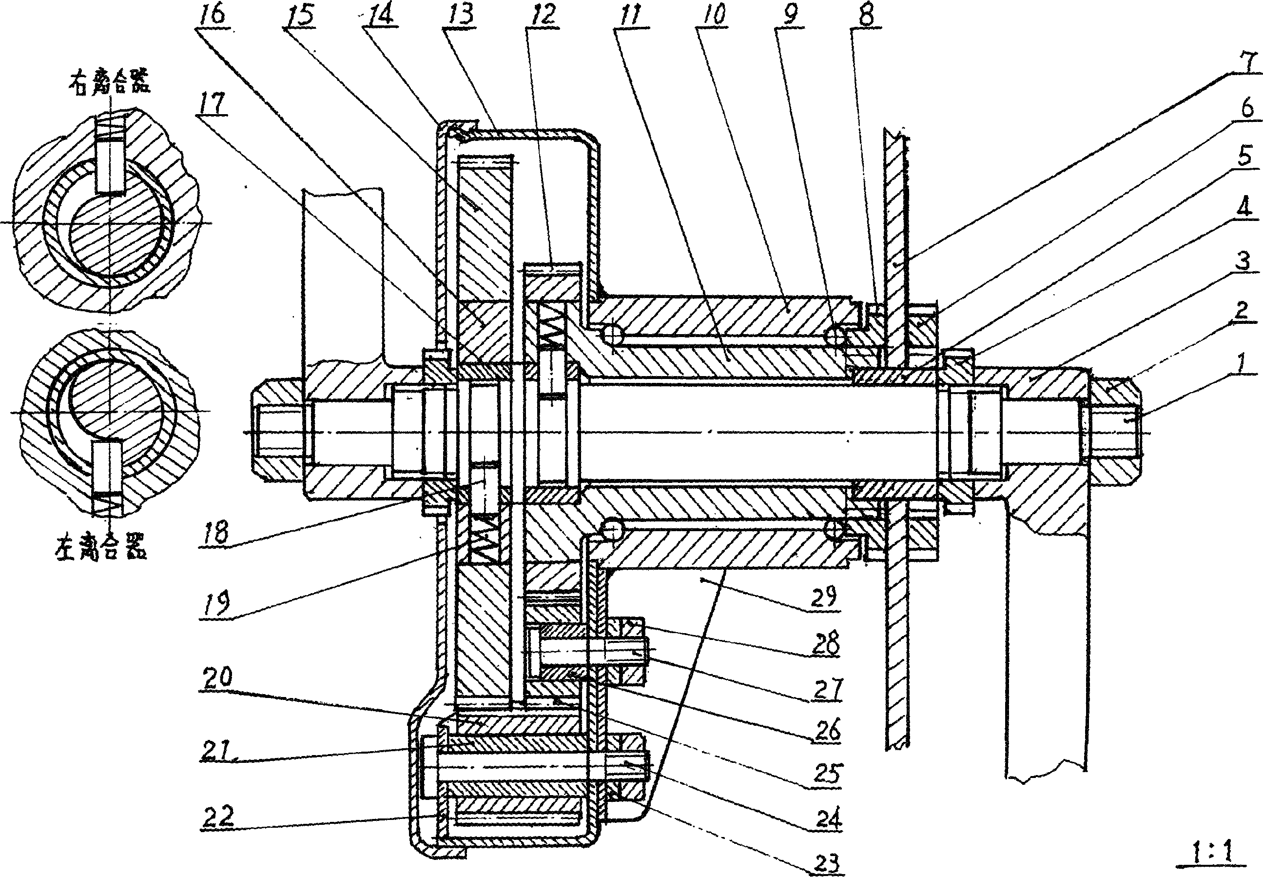
[0011] As shown in the figure, the whole mechanism is assembled in a circular gearbox composed of parts 13, 14, 22, 29 welded on the left side of part 10.

[0012] When the part 1 rotates forward, the part 18 of the right clutch drives the part 11 to rotate forward synchronously, and the part 7 (large sprocket) fixed on the part 11 also rotates together, so that the rear wheel of the bicycle is driven to rotate through the chain to make the vehicle move forward , which is the same as riding a bicycle normally, which is a speed. At the same time, the part 11 reverses the part 25 meshed with it, makes the part 20 meshed with the part 25 forward, and makes the part 16 meshed with the part 20 (that is, the bull gear) reverse. Because part 1 rotates forward and part 16 reverses, so the left clutch formed by part 16 and part 1 is in an overrunning state, and part 16 is in a no-load idling state.

[0013] When the part 1 reverses, the part 18 in the left clutch drives the part 16 to...


PUM


Abstract

The present invention is one kind of speed varying mechanism installed to cycle for altering the speed via changing the pedaling direction. The speed varying mechanism consists of one circular gear box installed to the left side of the pedal shaft and with punched casing, middle shaft, two gears in the tooth ratio of 5 to 3, two oppositely installed overrunning clutches on the same shaft and two transition gears. The present invention has the advantages of altering speed only by changing the pedaling direction, simple structure, reasonable design, easy manufacture and low cost, and is suitable for pedaled cycles and wheeled chair.

Description

Technical field: [0001] The invention relates to a speed change mechanism, specifically a device suitable for being assembled on a pedal (hand crank) vehicle, which can realize speed change without any operation while the vehicle is running. Background technique: [0002] Existing bicycle (mainly bicycle) has several types of speed changers, and these speed changers all need to operate gear shifting with hands when shifting. Because the distance between the operating handle and the shifting part is far away and the wire rope is used to affect it, it often causes operation failure and cannot shift gears. [0003] This device is just very simple, does not need to do any operations for shifting, and there is no such thing as gear shifting. That is, forward pedaling is a kind of speed, and reverse pedaling is another kind of speed. The ratio of the two speeds can be designed as 1:1.5; 1:1.7; 1:2, etc. Taking many factors into consideration, the ratio of the two speeds of the d...

Claims


Application Information

Patent Timeline
IPC IPC(8): B62M11/06
Inventor 游志成
Owner 游志成
Why Eureka
Try Eureka