Boiling heat-transfer tube and making method thereof

A manufacturing method and technology for heat transfer tubes, which are used in heat transfer modification, refrigerators, tubular elements, etc., can solve the problems of inability to exert performance and poor wettability of refrigerant liquid, and achieve the promotion of boiling and good heat transfer. performance effect

Inactive Publication Date: 2005-06-08
HITACHI CABLE
View PDF4 Cites 15 Cited by
  • Summary
  • Abstract
  • Description
  • Claims
  • Application Information

AI Technical Summary

Problems solved by technology

Therefore, the upper heat transfer tubes are covered with bubbles formed by boiling caused by the lower heat transfer tubes, so the wettability of the refrigerant liquid deteriorates and the original performance cannot be exhibited.

Method used


Image

  • Boiling heat-transfer tube and making method thereof
  • Boiling heat-transfer tube and making method thereof
  • Boiling heat-transfer tube and making method thereof

Examples


Embodiment Construction

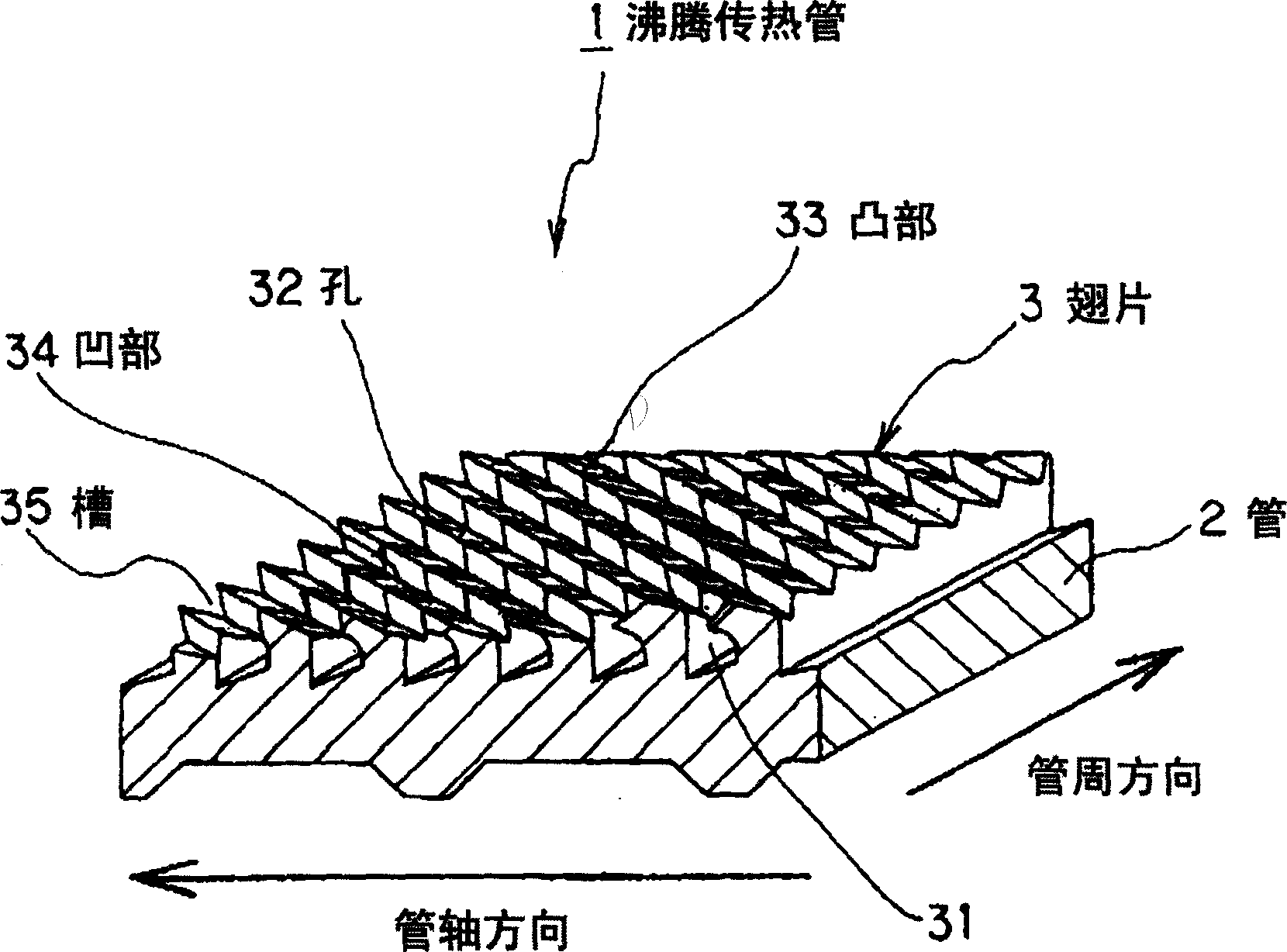
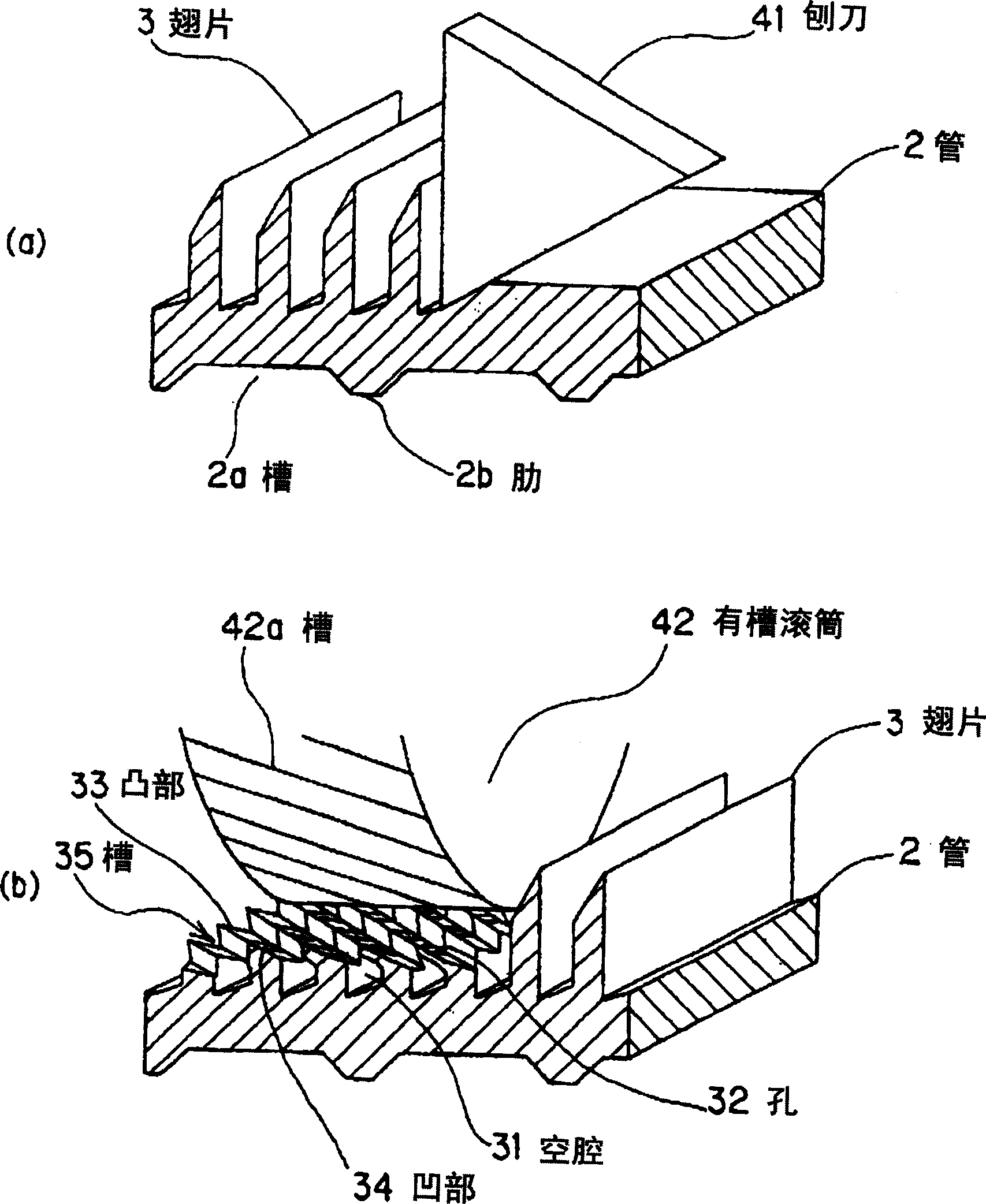
[0022] figure 1 and figure 2 Shown is the boiling heat transfer tube of the embodiment of the present invention. The boiling heat transfer tube 1 structurally includes a tube 2 made of metal tubes such as copper, copper alloy, aluminum, etc. with excellent heat transfer performance, and fins 3 scooped near the surface of the tube 2 with a processing tool such as a planer.

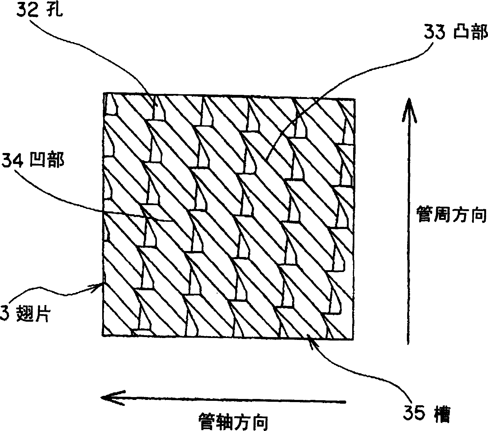
[0023] The fin 3 has a spiral or annular cavity 31 formed in the circumferential direction of the tube 2 and holes 32 for communicating the cavity 31 with the outside (refrigerant liquid) at predetermined intervals. The surface of the fin 3 is a concavo-convex surface in which a convex portion 33 and a concave portion 34 are sequentially formed between the holes 32 , and one side of the convex portion 33 is provided as an inclined surface.

[0024] The cavity 31 is continuous in the circumferential direction of the tube, and is perpendicular to or inclined to the tube axis. The groove 35 formed by the ...


PUM


Abstract

PROBLEM TO BE SOLVED: To provide a boiling heat transfer tube having improved heat transfer performance by improving the wettability of refrigerant liquid to accelerate nuclear boiling, and to provide its manufacturing method. SOLUTION: On the outer peripheral face of a tube 2, fins 3 are formed by continuing spading and bending in such a manner that a spiral or annular cavity portion 31 is formed in the circumferential direction thereof. At the front ends of the fins 3, grooves 35 are formed with protruded portions 33 and recessed portions 34 by using a grooved roll for applying suppressing pressure. The grooves 35 have holes 32 at preset spaces in communication with the outside (refrigerant liquid). COPYRIGHT: (C)2005,JPO&NCIPI

Description

technical field [0001] The present invention relates to an ebullient heat transfer tube and a manufacturing method thereof, and particularly relates to an ebullient heat transfer tube capable of improving the heat transfer performance of a heat transfer tube that heats and boils a refrigerant liquid in a state of being immersed in the refrigerant liquid of a large refrigerator Tubes and methods for their manufacture. Background technique [0002] Larger freezers, such as turbo freezers or spiral freezers, have an evaporator in which boiling heat transfer tubes are used. The boiling heat transfer tube is used to heat the boiling refrigerant liquid, which is immersed in the refrigerant liquid in the evaporator. Efficient heat exchange is very important to the ebullient heat transfer tube, so it has been proposed to form spiral fins (fin fins) on the outer peripheral surface of the tube. For example, fins are formed on the outer surface of the tube, the tops of the fins are p...

Claims


Application Information

Patent Timeline
IPC IPC(8): B23P15/26B21D22/08B21D53/06F25B39/02F28F1/36F28F1/40F28F13/02F28F13/18
CPCB21J5/068F28F13/187
Inventor 中井刚栗田雅春
Owner HITACHI CABLE
Why Eureka
Try Eureka