
Charging unit for image forming apparatus

一种充电部件、充电设备的技术,应用在电气元件、应用电荷图形的电记录工艺、电晕放电装置等方向,能够解决电阻分布不均匀、感光部件表面电位分布不均匀等问题

Inactive Publication Date: 2010-09-08
CANON KK
View PDF3 Cites 0 Cited by
  • Summary
  • Abstract
  • Description
  • Claims
  • Application Information

AI Technical Summary

Problems solved by technology

However, if the magnetic brush is uneven in the gap between the photosensitive member and the downstream device, the distribution of electrical resistance on the surface of the photosensitive member is not uniform, so after the device leaves, the potential distribution on the surface of the photosensitive member is not uniform

Method used


Image

  • Charging unit for image forming apparatus
  • Charging unit for image forming apparatus
  • Charging unit for image forming apparatus

Examples


example 1

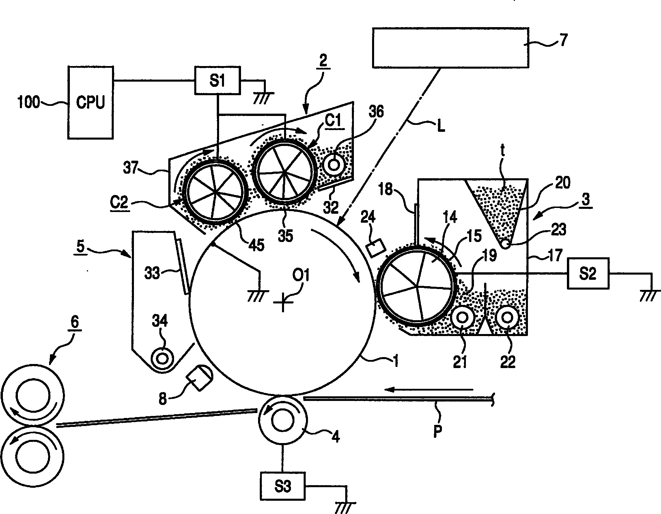
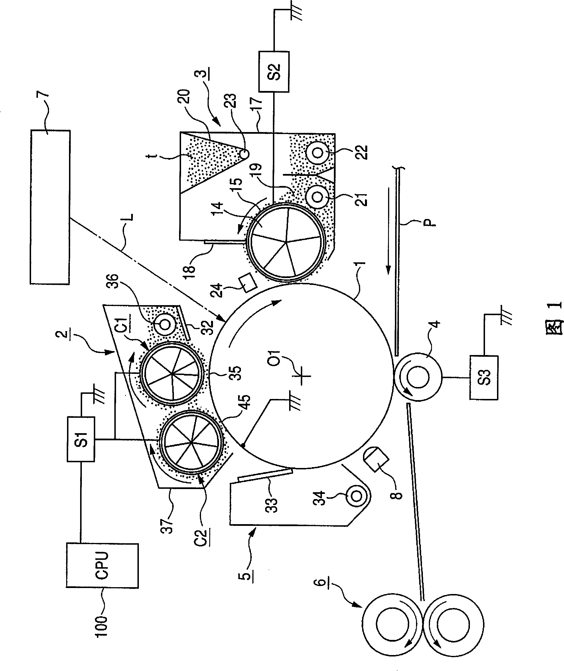
[0035] Fig. 1 outlines the structure of the image forming apparatus of Example 1 schematically.

[0036] (1) The overall structure of the imaging device

[0037] The image forming apparatus of the present invention is a laser beam printer having a plurality of magnetic brush charging devices for transfer electrophotographic processing.

[0038] In FIG. 1 , a rotary drum-type electrophotographic photosensitive member 1 (hereinafter referred to as a photosensitive drum 1 ) as an image bearing member is driven so as to rotate clockwise in the direction of an arrow at a prescribed peripheral speed. The photosensitive drum 1 in Example 1 was made of amorphous silicon (a-Si).

[0039] The multi-magnetic brush charging unit 2 serves as a charging device having a plurality of magnetic brush charging devices. It uniformly charges the surface of the rotary photosensitive drum 1 with a specified potential of a specified polarity (-700 V in Example 1). The magnetic brush charging unit ...

example 2

[0116] In Example 2, an organic photosensitive member was used as the photosensitive drum 1 . Other features are the same as those of the device in Example 1, and the details will not be repeated.

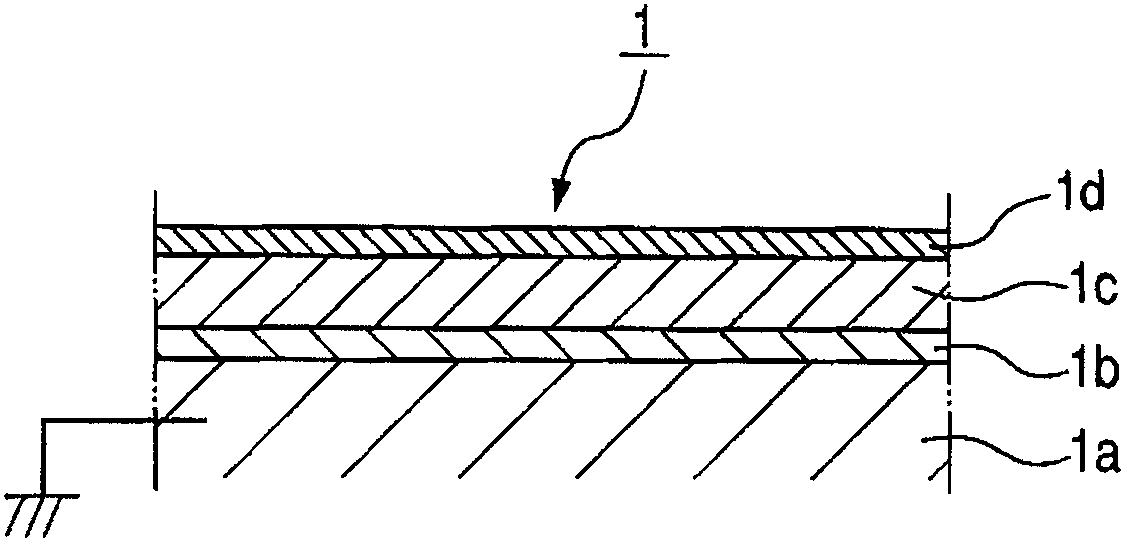
[0117] The photosensitive drum 1 in Example 2 as an image bearing member was manufactured using a negatively chargeable OPC photosensitive member. It has a layered structure comprising a grounded aluminum drum base 1a (30 mm in diameter) on which first to fifth functional layers 1e to 1i are sequentially coated, as shown in FIG. 5 .

[0118] The first layer 1e supported by the drum base 1a is an undercoat layer with a thickness of about 20 [mu]m for smoothing defects etc. on the drum base 1a and preventing moiré due to reflection of the exposure laser beam.

[0119] The second layer 1f is a positive charge injection layer for preventing the positive charges injected from the aluminum drum base 1a from canceling the negative charges on the surface of the photosensitive member. It ...


PUM


Abstract

A charging apparatus which can prevent deposition of magnetic particles of an upstream charging means on a photosensitive member, comprises: an image bearing member which supports an image, a first charging means which includes a magnetic member for generating magnetism, has a holding member for holding magnetic particles by a magnetic force, and charges the image bearing member by bringing the magnetic particles in contact with the image bearing member; the magnetic member of the first charging means having a magnetic pole facing the image bearing member, and also having a peak magnetic force position downstream, in the image bearing member rotation direction, relative to a position at which the image bearing member comes closest to the holding member, and a second charging means which includes a magnetic member for generating magnetism, has a holding member for holding magnetic particles by magnetic force, is located at the tail end in the image bearing member rotation direction butbefore a position at which an image is formed on the image bearing member, and charges the image bearing member, after charged by the first charging means, by bringing the magnetic particles in contact with the image bearing member; the magnetic member of the second charging means having a magnetic pole facing the image bearing member, and also having a peak magnetic force position upstream, in the image bearing member rotation direction, relative to a position at which the image bearing member comes closest to the holding means.

Description

technical field [0001] The present invention relates to an image forming apparatus having a charging device for uniformly charging an image bearing member by using conductive magnetic particles suitable for an electrophotographic copier, particularly an electrophotographic printer. Background technique [0002] (1) Charging device [0003] In order to obtain a specified potential of a specified polarity on the carrier surface, charging devices that perform uniform charging processing (including erasing processing) on ​​image bearing members such as electrophotographic photosensitive members, electrostatic recording dielectrics, and the like are classified into two categories: non-contact types and contact type. [0004] a) Non-contact charging device [0005] A corona charging device (or discharging device) is a non-contact charging device facing an image bearing member (hereinafter referred to as a photosensitive member) in a non-contact manner to expose the surface of th...

Claims


Application Information

Patent Timeline
Patent Type & Authority Patents(China)
IPC IPC(8): G03G15/02G03G15/00G03G5/08G03G5/147
CPCG03G2215/022G03G15/0241
Inventor 井上亮
Owner CANON KK
Learn More