Optical fiber composite electrical power cable

一种电力电缆、光纤复合的技术,应用在电力电缆、绝缘电缆、通信电缆等方向,能够解决不能精确地测量预定区域温度等问题

Inactive Publication Date: 2005-06-08
LG CABLE INC
View PDF5 Cites 41 Cited by
  • Summary
  • Abstract
  • Description
  • Claims
  • Application Information

AI Technical Summary

Problems solved by technology

In this case, the fiber or catheter may be bent or tilted to one side beyond its design optimum, thus not being able to accurately measure the temperature of the intended area

Method used


Image

  • Optical fiber composite electrical power cable
  • Optical fiber composite electrical power cable
  • Optical fiber composite electrical power cable

Examples


Embodiment 1

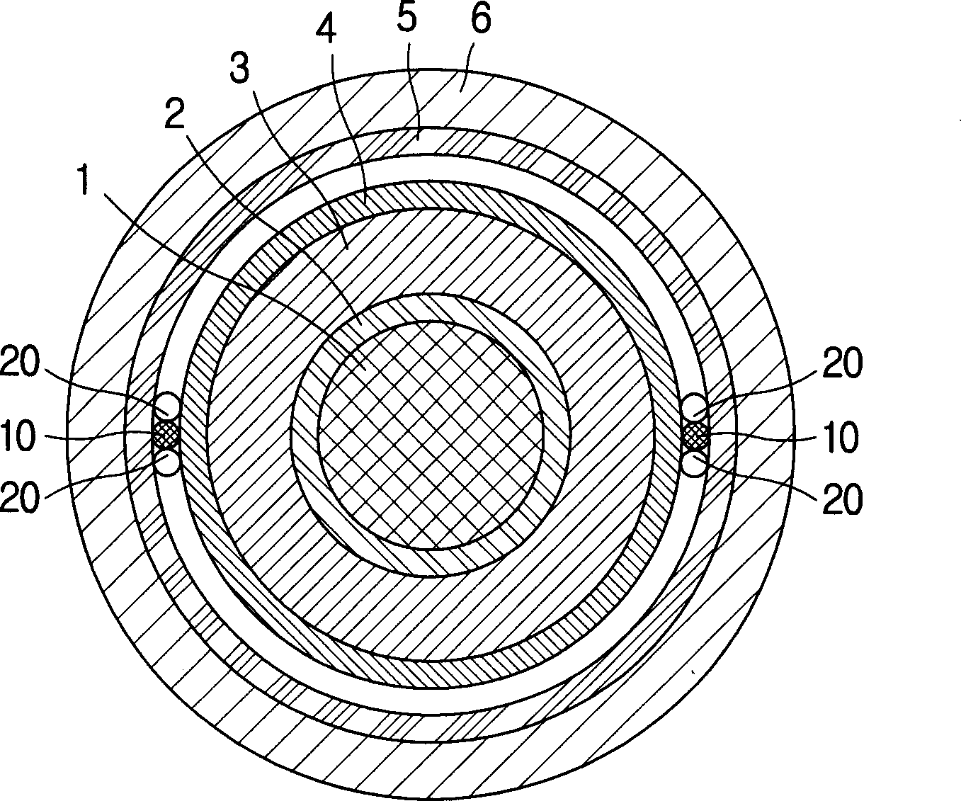
[0028] figure 1 is a sectional view showing the optical fiber composite power cable according to the first embodiment of the present invention. refer to figure 1 , the cable includes a core 1, 2, 3, and 4 located at the center of the cable, sheaths 5 and 6 covered around the core, and optical components 10 and 20 placed between the core and the sheath.

[0029] The core comprises a central conductor 1, an inner semiconducting layer 2 covering the periphery of the central conductor 1, an insulating layer 3 covering the periphery of the inner semiconducting layer 2, and an outer semiconducting layer 4 covering the periphery of the insulating layer 3 .

[0030] The central conductor 1 guides and transmits the current from the substation to the electrical equipment, and when high voltage is applied to this conductor, the semiconducting layers 2 and 4 function to prevent the accumulation of high electric fields. Furthermore, the insulating layer 3 prevents dielectric breakdown. ...

Embodiment 2

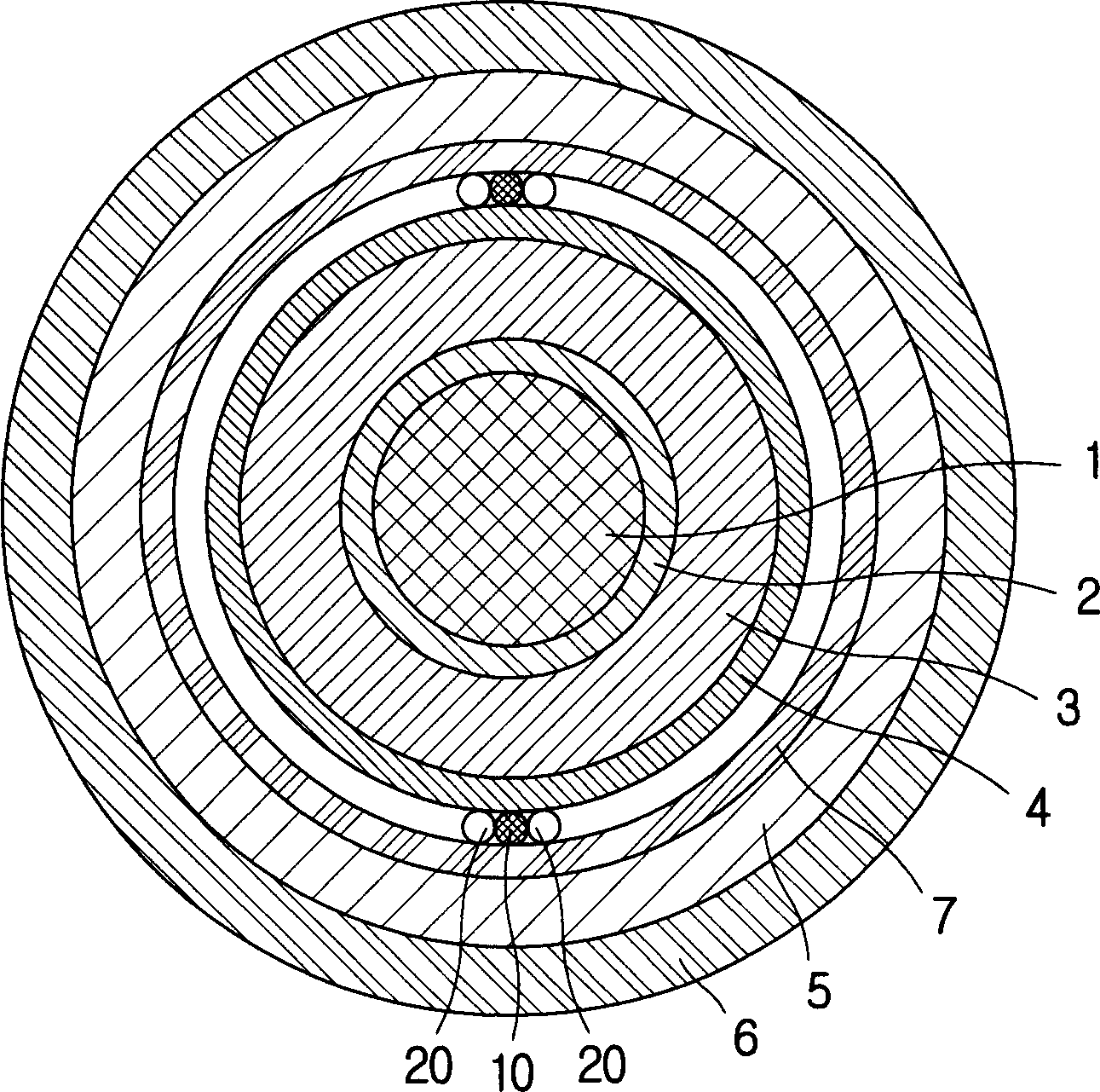
[0040] image 3 is a sectional view showing an optical fiber composite power cable according to a second embodiment of the present invention. This embodiment is similar to the previous embodiment in that the cable comprises a core 1, 2, 3 and 4, a sheath 5, 6 and 7 overlying the core, and an optical assembly 10 and 20. In particular, cores 1, 2, 3 and 4 and optical assemblies 10 and 20 do not differ in any way compared to the first embodiment. However, the detailed structure of the sheaths 5, 6 and 7 differs from the first embodiment as follows.

[0041] In addition to the metal sheath layer 5 and the protective layer 6 , the sheath of this embodiment also includes a fixing belt 7 . This fixing band 7 has the function of fixing the optical components 10 and 20 to the outer semiconducting layer 4 of the core. As for the fixing tape 7, a semiconductor tape or an insulating tape can be used. In particular, in the case where the metal sheath layer 5 is a corrugated aluminum t...

Embodiment 3

[0044] Figure 4 is a sectional view showing an optical fiber composite power cable according to a third embodiment of the present invention. This embodiment is also similar to the first embodiment, ie the cable comprises cores 1, 2, 3 and 4, jackets 6 and 8 covering the cores, and optical assemblies 10 and 20 placed between the cores and jackets. In particular, cores 1, 2, 3 and 4 and optical assemblies 10 and 20 do not differ in any way compared to the first embodiment. However, the detailed structures of the sheaths 6 and 8 are different from the first embodiment as follows.

[0045] The sheath of this embodiment comprises at least one metal wire 8 helically wound around the outer semiconductive layer 4 of the core and extending in the longitudinal direction of the cable, and a plastic protective layer 6 covering the metal wire layer 8 .

[0046] refer to Figure 4 , wires 8 made of copper or aluminum are accommodated in spaces outside the cores 1 , 2 , 3 and 4 for accom...


PUM


Abstract

The present invention discloses an underground power cable with an optical fiber for measuring temperature distribution. In this power cable, an optical fiber for measuring temperature distribution is housed in a stainless steel tube with high strength, and an optical fiber guide is placed between the core and the sheath of the cable. When the fiber optic guide is placed in the power cable, a supporting material with a relatively lower strength than the fiber guide is also provided in the cable to prevent the optical fiber from being damaged by external force and prevent the inner insulating layer from being damaged by the fiber guide. In addition, fixing straps can be added to fix the contact between the fiber guide and the core, so as to prevent the fiber guide from being severely bent or tilted to one side when the cable is bent.

Description

technical field [0001] The invention relates to an underground power cable for transmitting electric power and laid underground, especially an underground power cable with an optical fiber sensor for measuring the distribution temperature of the cable. Background technique [0002] Generally, the temperature of the underground power cable rises when current is applied to the underground power cable, and the ampacity can be calculated based on the highest temperature the underground power cable can withstand. Therefore, when the underground power cable is working, it is very important to measure the temperature of the underground power cable carrying current. However, since it is practically impossible to measure the temperature of a conductor while the underground power cable is carrying current, optical fibers for temperature measurement are usually used. [0003] For example, Korean Patent Publication No. 2003-45864 discloses a system for calculating the temperature of an...

Claims


Application Information

Patent Timeline
Patent Type & Authority Applications(China)
IPC IPC(8): H01B11/22G01K11/32G02B6/44H01B7/17H01B7/32H01B9/00
CPCG02B6/4416H01B7/324H01B11/22
Inventor 吴德镇权泳国李仁镐南晰铉李秀吉郑在容李惠园
Owner LG CABLE INC
Why Eureka
Try Eureka