Supercharge Your Innovation With Domain-Expert AI Agents!

Radiographic apparatus

一种射线照相、设备的技术,应用在X射线设备、用于放射诊断的仪器、仪器等方向,能够解决过量数据处理负载等问题

Active Publication Date: 2005-06-22
SHIMADZU SEISAKUSHO LTD
View PDF1 Cites 5 Cited by
  • Summary
  • Abstract
  • Description
  • Claims
  • Application Information

AI Technical Summary

Problems solved by technology

[0004] However, the conventional X-ray radiography apparatus has a problem in that an excessive data processing load is caused by a mechanical displacement occurring between the rotation axis RA and the radiation emission axis XA of the X-ray tube 51 and the X-ray detector 52
This causes the inconvenience that efficient calculation processing cannot be performed by continuously reading the data to be used once at a time, and temporarily storing the data in a cache memory that provides high-speed data transfer

Method used


Image

  • Radiographic apparatus
  • Radiographic apparatus
  • Radiographic apparatus

Examples


Embodiment Construction

[0049] Embodiments of the present invention will be described below with reference to the drawings.

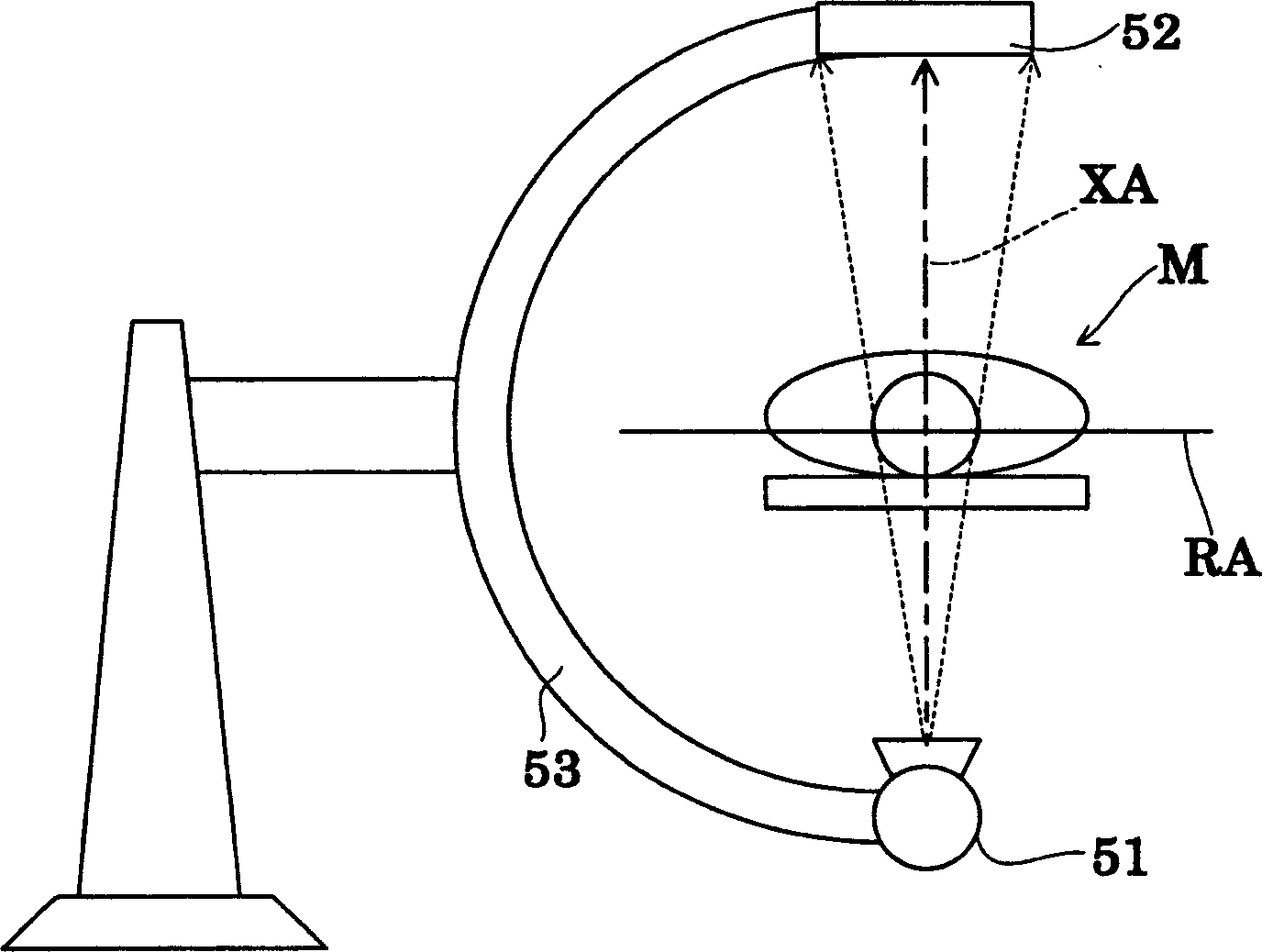
[0050] The apparatus in this embodiment is a C-arm driven X-ray radiography apparatus of the type that emits X-rays in a cone beam, and is used in medical institutions such as hospitals. Figure 4 is a block diagram showing the overall configuration of an X-ray radiography apparatus (hereinafter, simply referred to as “radiography apparatus”). Figure 5 is a schematic diagram showing the mechanical arrangement of the X-ray image pickup system in the apparatus according to the present invention. The X-ray radiographic apparatus corresponds to the radiographic apparatus of the present invention.

[0051] like Figure 4 As shown, the radiographic apparatus in this embodiment includes: an X-ray tube 1 for emitting X-rays in a cone beam; a flat panel type X-ray detector 2 (hereinafter, appropriately referred to as "FPD 2"), Used to inspect transmitted X-ray images. An X-ray tub...


PUM


Abstract

The reconstruction process of the pixel data for processing the tomographic image data uses a concise reconstruction algorithm based on the fact that the axis of the X-ray emission axis always exists in a direction orthogonal to the rotation axis of the X-ray tube and the FPD. on flat surface. During the reconstruction process, correction parameters are applied to the reconstruction algorithm for correcting the mechanical displacement occurring between the rotation axis of the X-ray tube and the X-ray emission axis. Therefore, by simple data processing for setting correction parameters for the reconstruction algorithm, errors due to mechanical displacement can be avoided without impairing the reduction of data processing load on the reconstruction algorithm.

Description

technical field [0001] The present invention relates to a radiographic apparatus having radiation emitting means for emitting radiation in a cone-shaped beam and two-dimensional radiation detecting means for detecting transmitted radiation images. The radiation emitting means and the radiation detecting means are rotatable about a rotation axis provided by a line extending through the object to be inspected for scanning important parts of the object. The pixel data of the cross-sectional image is input to a reconstruction process based on radiation image detection data output from the radiation detection device in response to radiation emissions in the cone beam, and on a reconstruction algorithm. More particularly, the present invention relates to a technique for reducing a data processing load due to mechanical displacement occurring between a rotation axis and a radiation emission axis of a radiation emitting device and a radiation detecting device. Background technique ...

Claims


Application Information

Patent Timeline
Patent Type & Authority Applications(China)
IPC IPC(8): A61B6/03G06T11/00
CPCA61B6/032A61B6/4085A61B6/4233A61B6/4405A61B6/4441A61B6/587G06T11/005Y10S378/901A61B6/03
Inventor 森田尚孝
Owner SHIMADZU SEISAKUSHO LTD
Features
  • R&D
  • Intellectual Property
  • Life Sciences
  • Materials
  • Tech Scout
  • Unparalleled Data Quality
  • Higher Quality Content
  • 60% Fewer Hallucinations
Learn More