
Cab of construction machinery

A technology for construction machinery and cabs, which is applied in the field of cabs, can solve problems such as cab deformation, and achieve the effects of improving support strength, easy handling, and improving reliability and safety

Active Publication Date: 2005-06-22
NIHON KENKI CO LTD
View PDF1 Cites 3 Cited by
  • Summary
  • Abstract
  • Description
  • Claims
  • Application Information

AI Technical Summary

Problems solved by technology

[0009] Therefore, in the structure in which the floor and the rear part of the cab body are connected by the reinforcing body described in Patent Document 1, there is a possibility that the cab will be damaged due to the load concentrated on the root of the center pillar and the load acting to twist the center pillar. serious deformation problem

Method used


Image

  • Cab of construction machinery
  • Cab of construction machinery
  • Cab of construction machinery

Examples


Embodiment Construction

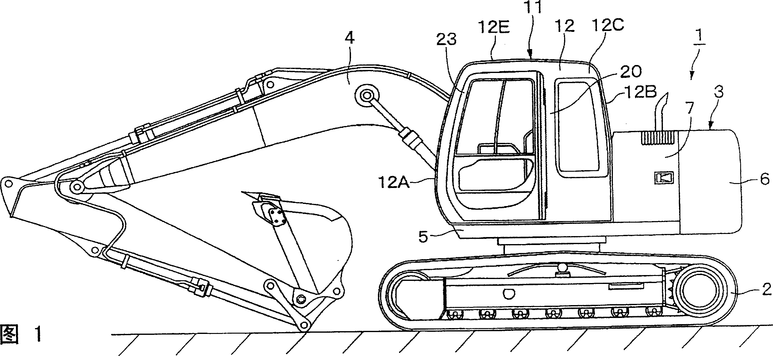
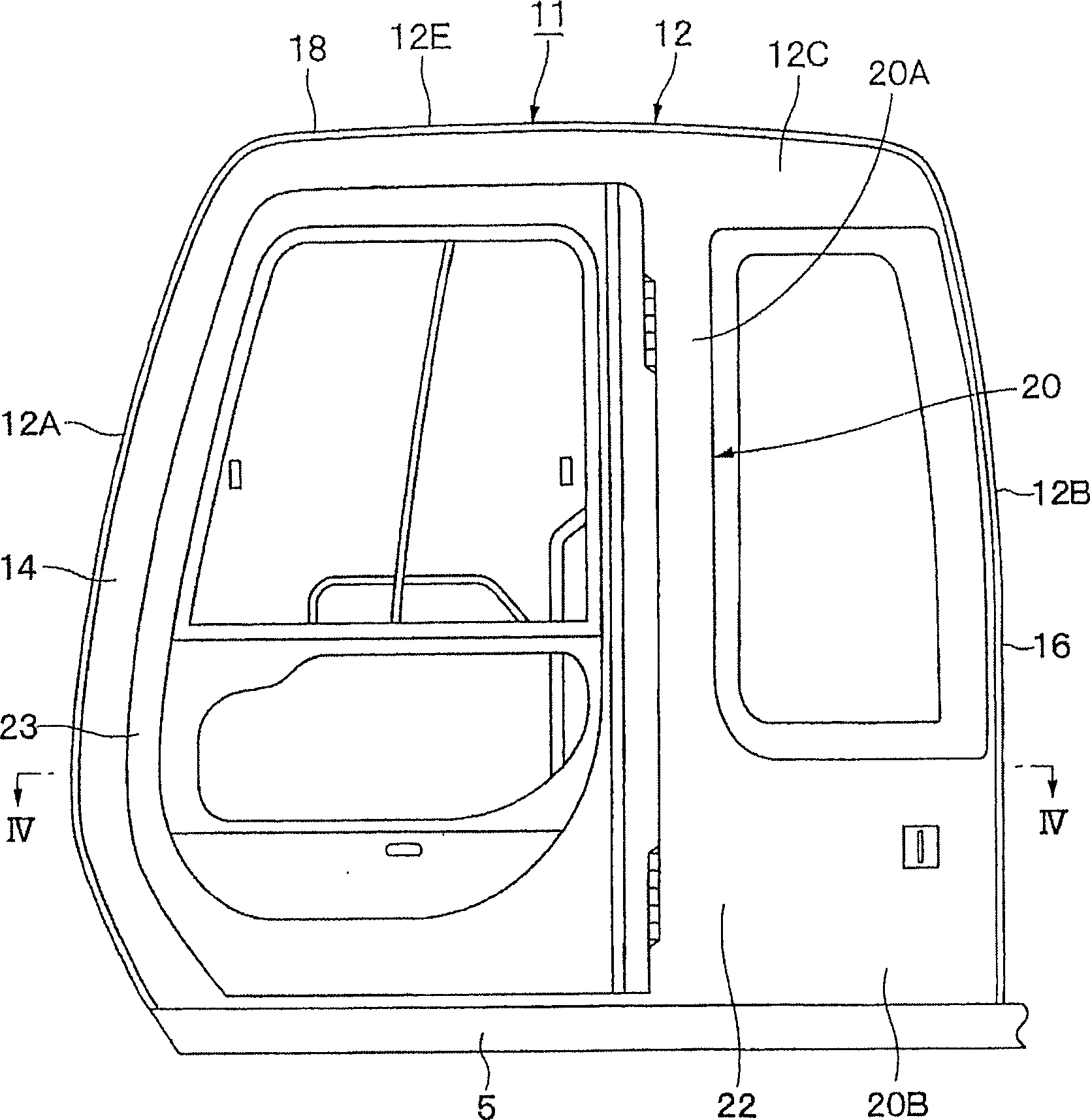
[0046] Hereinafter, a construction machine cab according to an embodiment of the present invention will be described in detail with reference to FIGS. 1 to 8 by taking a cab mounted on a crawler-type hydraulic excavator as an example.

[0047] In FIG. 1, 1 is a crawler-type hydraulic excavator as a construction machine. The hydraulic excavator 1 is roughly composed of a self-propelled lower traveling body 2, which is rotatably mounted on the lower traveling body 2, and travels with the lower part. The bodies 2 collectively constitute a revolving upper body 3 of a vehicle body, and are provided on the front side of the revolving upper body 3 so as to be capable of pitching and pitching, and constitute a working device 4 for performing earthwork excavation work and the like.

[0048] In addition, the upper revolving body 3 is roughly composed of a revolving frame 5, and a cab 11, which will be described later, is mounted on the front left side of the revolving frame 5, and a coun...


PUM


Abstract

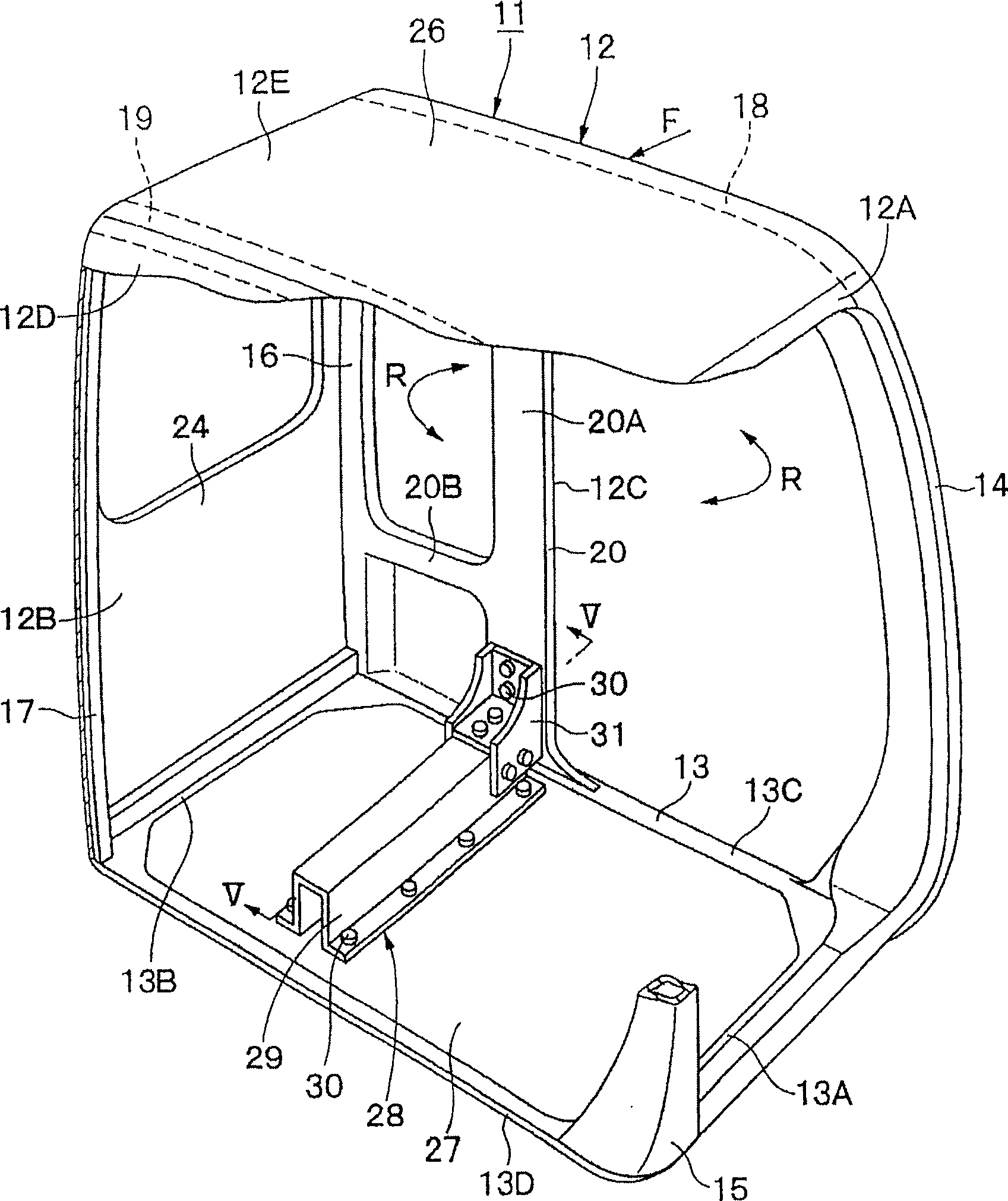
PROBLEM TO BE SOLVED: To heighten the strength against the load acting on the root part of a center pillar and the load acting so as to twist the center pillar and enhance the stiffness of a cab box. SOLUTION: A cab 11 includes a reinforcing device 28 consisting of a floor plate reinforcing member 29 extending to the left and right on the floor plate 27 of the cab 11 and heightening the strength of the floor plate 27 and a coupling member 31 to couple the left end of the floor plate reinforcing member 29 with the center pillar 20 of the cab box 12. Accordingly the reinforcing device 28 can strengthen the root part of the center pillar 20 upon reinforcement of the floor plate 27, the strength of the cab box 12 can be heightened both for the load F acting from the left on the center pillar 20 and the load R acting so as to twist the center pillar 20.

Description

technical field [0001] The present invention relates to a cab provided on a construction machine such as a hydraulic excavator, and particularly relates to a cab for a construction machine in which a center pillar is provided on a side surface of a cab casing. Background technique [0002] Generally, a hydraulic excavator as a construction machine is composed of a self-propelled undercarriage, an upper revolving body rotatably mounted on the undercarriage, and a working device provided on the front side of the upper revolving body so as to be able to pitch. . [0003] In addition, on the revolving frame constituting the upper revolving body, a cab in which an operator sits is provided on the left front side. The cab of this hydraulic excavator has a cab body with a front part, a rear part, a left side part, a right side part, and a roof part, a floor covering the cab body from the lower side, and an operation panel installed on the floor. driver's seat. [0004] In additi...

Claims


Application Information

Patent Timeline
Patent Type & Authority Applications(China)
IPC IPC(8): E02F9/16B62D25/04B62D25/08B62D33/06
CPCB60Y2200/412B62D33/0617E02F9/16E02F9/163
Inventor 小松和则
Owner NIHON KENKI CO LTD
Learn More