Fuel jetting device used in internal combustion engine

A technology for a fuel injection device and a fuel injection valve, which is applied in the directions of a fuel injection device, a special fuel injection device, a fuel injection pump, etc., can solve problems such as troubles, and achieve the effects of simple structure, simple structure, and space saving.

Inactive Publication Date: 2005-06-22
ROBERT BOSCH GMBH
View PDF1 Cites 3 Cited by
  • Summary
  • Abstract
  • Description
  • Claims
  • Application Information

AI Technical Summary

Problems solved by technology

but it's a lot of work

Method used


Image

  • Fuel jetting device used in internal combustion engine
  • Fuel jetting device used in internal combustion engine
  • Fuel jetting device used in internal combustion engine

Examples


Embodiment Construction

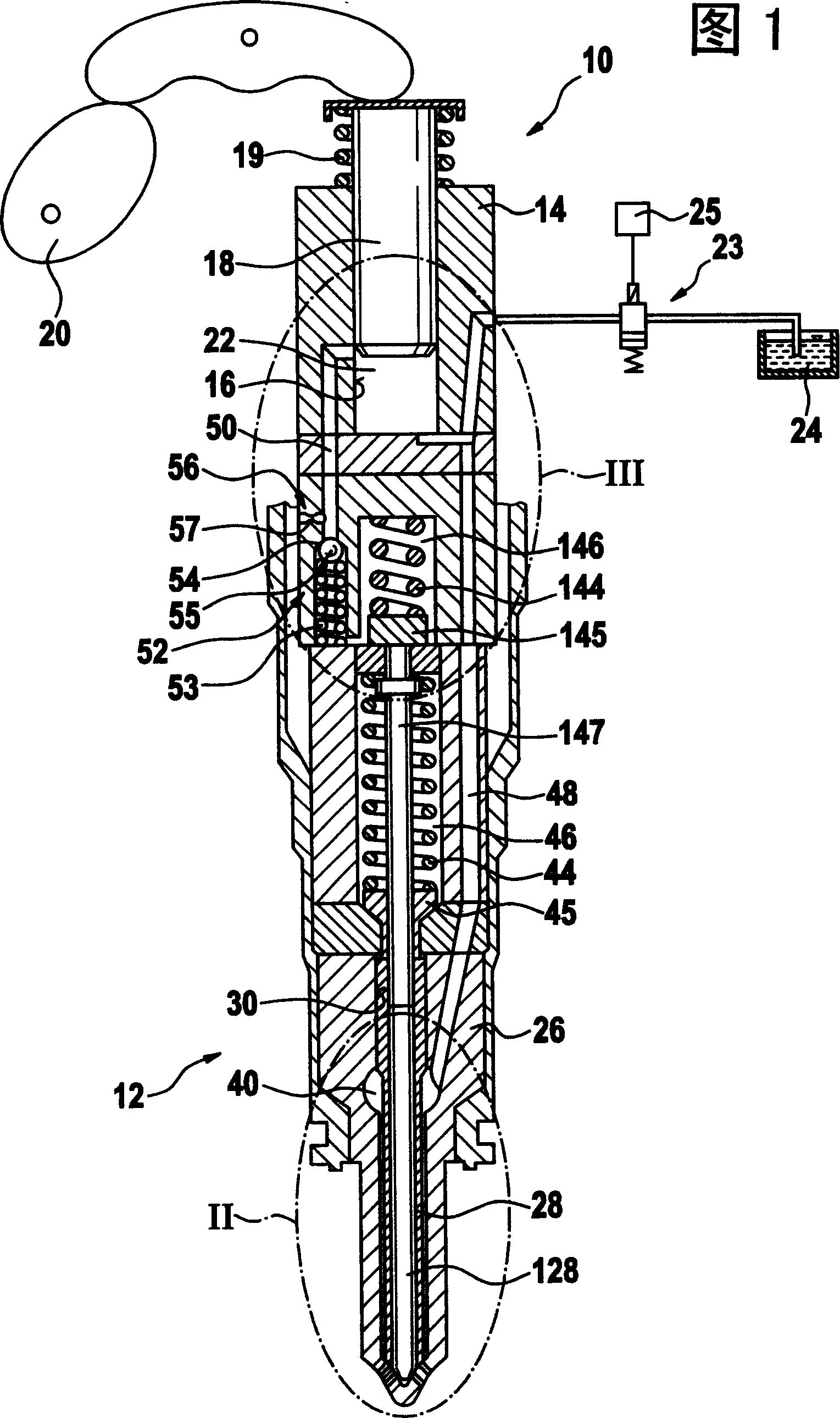
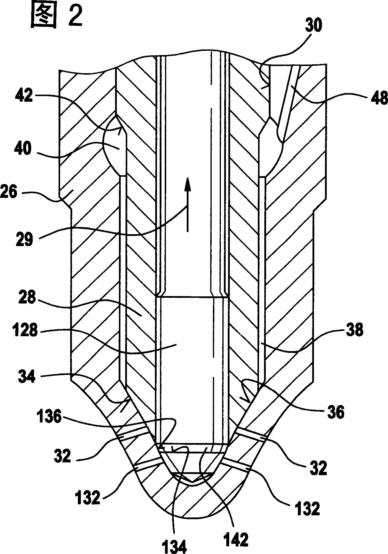
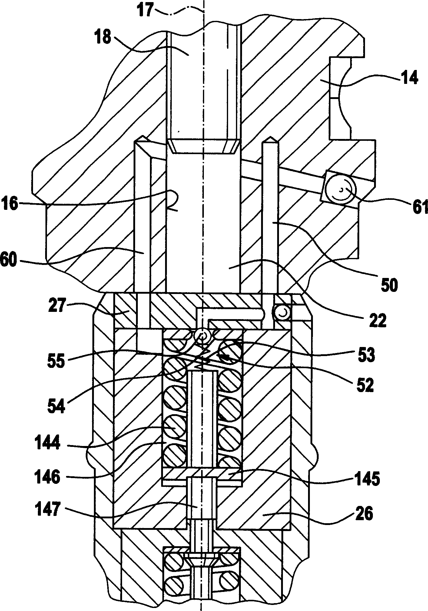
[0015] Figure 1 to Figure 6 A fuel injection device for an automotive internal combustion engine is described. The internal combustion engine is preferably a self-igniting internal combustion engine. The fuel injection system is designed as a pump-nozzle system or as a pump-line-nozzle system and has a high-pressure fuel pump 10 and a fuel injection valve 12 connected to the high-pressure fuel pump for each cylinder of the internal combustion engine. In the case of a pump-line-nozzle system, the high-pressure fuel pump 10 is situated remotely from the fuel injection valve 12 and is connected to the fuel injection valve via a line. In the described exemplary embodiment, the fuel injection system is designed as a pump-nozzle system, wherein the high-pressure fuel pump 10 and the fuel injection valve 12 are directly connected to one another and form a structural unit. The high-pressure fuel pump 10 has a pump piston 18 guided sealingly in a cylinder bore 16 of a pump body 14 ,...


PUM


Abstract

The device has a control space (146) providing a joint (50) with a pump operating space. The joint is opened and closed by respective small and big strokes of a pump piston (18). A control valve closes during the small stroke to feed the control space with an increased pressure and to keep an fuel injection valve component (128) in a closed position. The control space is separated from the pump operating space during the big stroke.

Description

technical field [0001] The invention relates to a fuel injection device for an internal combustion engine. Background technique [0002] A fuel injection device of this type is known from DE 101 62 384 A1. This fuel injection device has a high-pressure fuel pump and a fuel injection valve connected thereto for each cylinder of the internal combustion engine. The high-pressure fuel pump has a pump piston driven in a stroke movement by the internal combustion engine, the pump piston delimiting a pump working chamber in a cylinder bore, which is connected to the pressure chamber of the fuel injection valve. An electrically operated control valve is provided, via which the connection of the pump working chamber to the unloading area is controlled. The fuel injection valve consists of two injection valve elements, via which at least one injection opening is actuated by each valve element. A movable second injector element is accommodated within the hollow first injector elemen...

Claims


Application Information

Patent Timeline
Patent Type & Authority Applications(China)
IPC IPC(8): F02M45/08F02M57/02F02M59/26
CPCF02M57/023F02M45/086F02M59/265F02M2200/46
Inventor 彼得·伯兰德塞巴斯蒂安·坎内
Owner ROBERT BOSCH GMBH
Why Eureka
Try Eureka