Combined type phase-change energy accumulation solar water heater

A solar water heater and phase change energy storage technology, applied in the directions of solar thermal energy, solar thermal power generation, solar heating systems, etc., can solve the problems of limited hot water, limited use range of solar water heaters, and impossible to have too much volume, etc. Heat utilization, processing and safety and reliability, the effect of increasing the scope of use

Inactive Publication Date: 2005-06-29
周航
View PDF0 Cites 17 Cited by
  • Summary
  • Abstract
  • Description
  • Claims
  • Application Information

AI Technical Summary

Problems solved by technology

[0002] The solar water heaters in the prior art use water and other liquid substances as the heat exchange medium to directly transfer the heat absorbed by the collector to the water in the water tank, so the amount of hot water that can be provided is very limited, and usually the sunshine of a day is only The water in the supporting water tank is heated to a certain temperature, and the size of the water tank is limited by various factors such as heat transfer efficiency and space volume, so it is impossible to have too much volume, which limits the application of solar water heaters to a certain extent. scope of use

Method used


Image

  • Combined type phase-change energy accumulation solar water heater
  • Combined type phase-change energy accumulation solar water heater

Examples


Embodiment 1

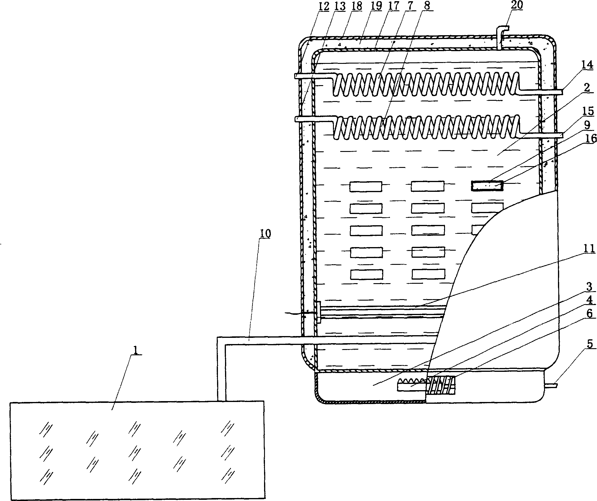
[0024] as attached figure 1 Shown, the composite phase change energy storage solar water heater of the present invention, its structure is made of heat collector 1 and water tank, wherein:

[0025] The heat collector 1 adopts a flat plate heat collector;

[0026] The water tank is composed of a water storage and heat preservation chamber 2 filled with a liquid heat exchange medium (water or oil) and a gas heating chamber 3 . The gas heating chamber 3 is arranged at the lower part of the water storage and heat preservation chamber 2, and a gas heating device 4 is arranged inside, and the gas connection pipe 5 protrudes to the outside of the casing of the gas heating chamber 3, and an air vent 6 is opened on the casing of the gas heating chamber 3 The top of the water storage and heat preservation chamber 2 is provided with two coil heat exchangers 7,8, and a plurality of phase change heat accumulators are arranged under the heat exchangers 7 and 8 in the water storage heat pre...

Embodiment 2

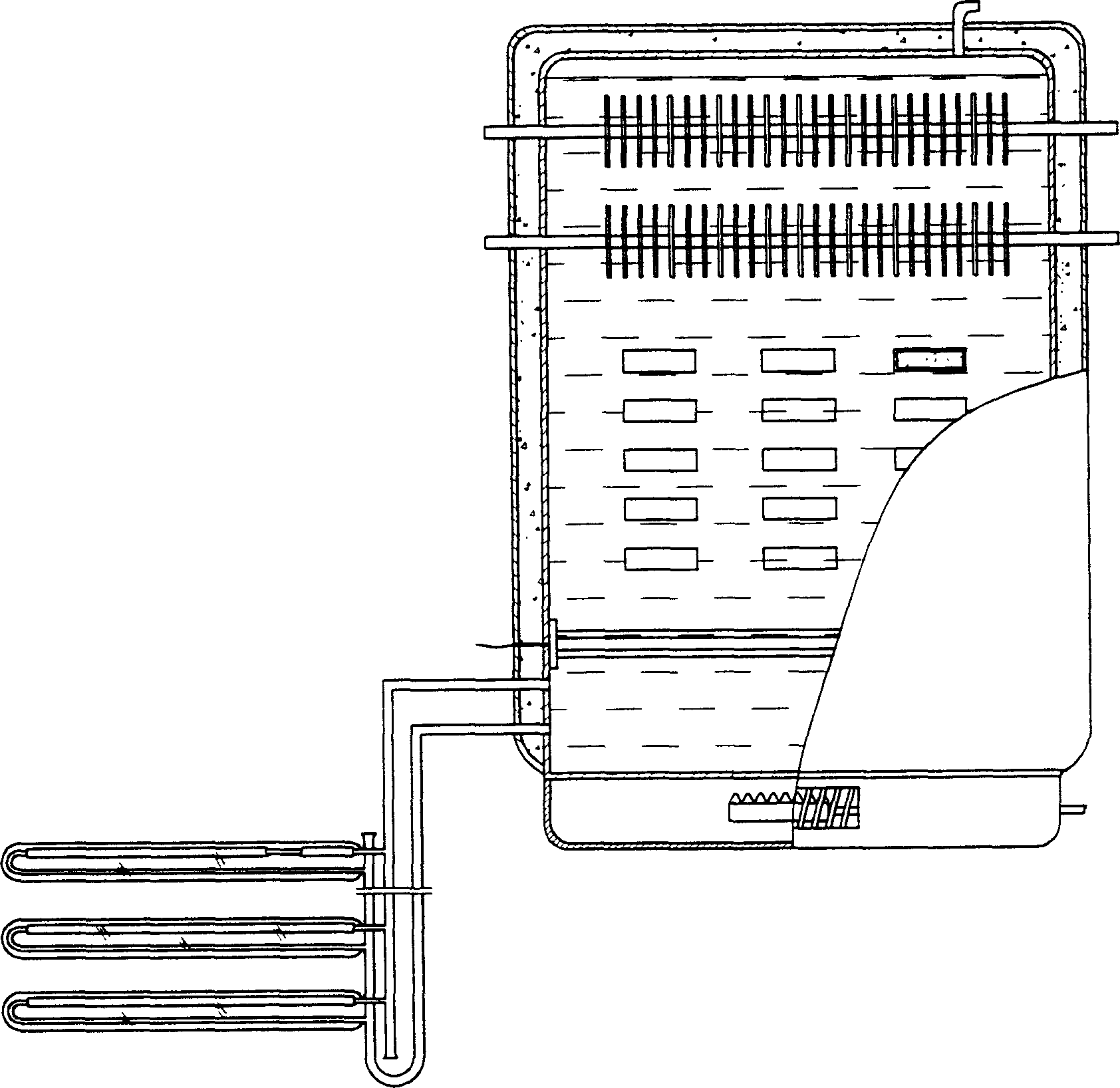
[0031] as attached figure 2 As shown, the heat exchanger in the water storage and heat preservation room adopts a fin heat exchanger; the heat collector is a vacuum tube heat collector; the heat collector and the water tank are connected by a medium microcirculation, and the heat medium of the heat collector Both ends of the circulation pipe are connected to the bottom of the water tank.

[0032] When the heat pipe is used to connect the heat collector and the water storage insulation room, the liquid heat exchange medium in the water storage insulation room absorbs the heat released from the condensation end of the heat pipe and does not enter the heat collector; the heat collector and the water storage are connected in the form of medium microcirculation In the heat preservation chamber, the liquid heat exchange medium in the water storage heat preservation chamber and the heat exchange medium in the heat collector circulate in order to achieve thermal balance, and the heat...


PUM


Abstract

The invention discloses a composite phase-change energy-storage solar water heater, which belongs to the field of solar water heater manufacturing. Its structure is composed of a heat collector and a water tank. The gas heating chamber of the device is arranged at the lower part of the water storage and heat preservation chamber, and the housing of the gas heating chamber is provided with a vent. There are air holes on the top of the shell of the heat preservation chamber, and the heat collector is connected to the bottom of the water storage heat preservation chamber through heat pipes. Compared with the prior art, the solar water heater of the present invention uses gas and electric energy as supplementary energy, and has the characteristics of high thermal efficiency, small water tank volume, and can supply multiple groups of hot water requirements such as heating and bathing at the same time, so it has good popularization and application value.

Description

technical field [0001] The invention relates to a solar water heater, in particular to a composite phase-change energy-storage solar water heater which uses gas and electric energy as supplementary energy sources and can simultaneously supply multiple sets of hot water such as heating. Background technique [0002] The solar water heaters in the prior art use water and other liquid substances as the heat exchange medium to directly transfer the heat absorbed by the collector to the water in the water tank, so the amount of hot water that can be provided is very limited, and usually the sunshine of a day is only The water in the supporting water tank is heated to a certain temperature, and the size of the water tank is limited by various factors such as heat transfer efficiency and space volume, so it is impossible to have too much volume, which limits the application of solar water heaters to a certain extent. scope of use. ...

Claims


Application Information

Patent Timeline
Patent Type & Authority Applications(China)
IPC IPC(8): F24H1/20F24H7/02F24S90/00
CPCY02E10/40
Inventor 周航
Owner 周航
Why Eureka
Try Eureka