

Heat transfer process for variable cross section intensive selfoscillatory flow heat pipe
A self-excited oscillation and variable section technology, which is applied in the field of heat exchange to achieve the effects of high heat transfer efficiency, easy processing and simple structure
Inactive Publication Date: 2005-06-29
NORTH CHINA ELECTRIC POWER UNIV (BAODING)
View PDF0 Cites 11 Cited by
- Summary
- Abstract
- Description
- Claims
- Application Information
AI Technical Summary
Problems solved by technology
Moreover, the convective heat transfer process between the working medium and the heat pipe wall is greatly enhanced by the action of the violent pulsating flow.
Method used
View moreImage
Smart ImageViewing Examples

Examples
Embodiment Construction
[0020] The two end regions of the variable cross-section self-excited oscillating flow heat pipe are in contact with the cold source and the heat source respectively. If the cold and heat sources are solid, the ends should be closely attached to the solid surface or embedded in the solid interior; if the cold and heat sources are gas or liquid, the end should be immersed in the fluid, and the contact area between the cold and heat source and the heat pipe is determined according to the amount of heat exchange.
Login to View More PUM
 Abstract
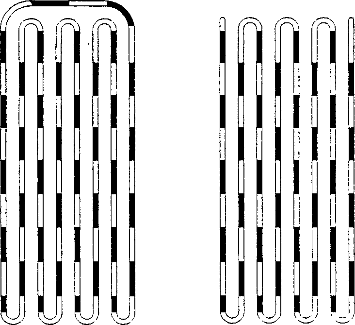
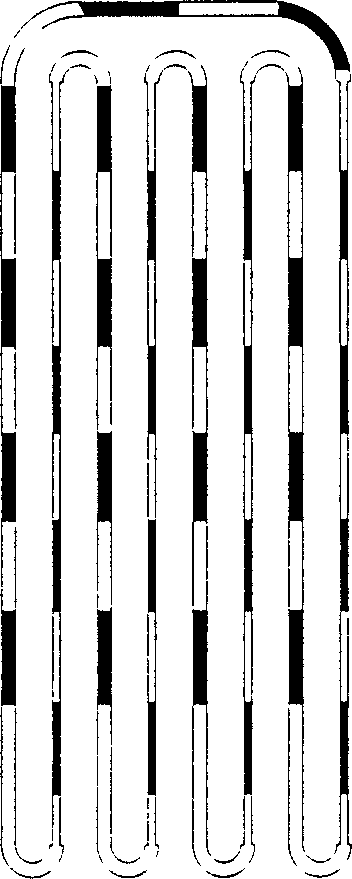
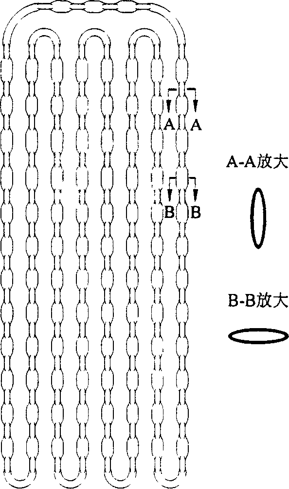
The invention provides a method for enhancing heat transfer of a self-excited oscillating flow heat pipe with a variable cross-section, and adopts a variable-section structure to enhance the heat transfer performance of the self-excited oscillating flow heat pipe. The self-excited oscillating flow heat pipe adopts two different tube diameters, and the tube diameters are changed and combined within the range of 0.5mm to 5.0mm, and are arranged alternately to form a self-excited oscillating flow heat pipe with variable cross-section, so that the fluid in the tube is heated at the heating end Then expand rapidly along the larger pipe diameter and flow to the condensation end; while the liquid condensed at the condensation end flows back to the heating end along the thinner pipe; due to the different curvature radii of the large and small pipe diameters, the surface tension generated by the liquid film Also different, the additional cycle power thus obtained. The present invention adopts the special-shaped section structure type and can also be elliptical, spiral, wedge-shaped or irregular. The invention has the advantages of high heat transfer efficiency, simple structure and easy processing.
Description
technical field [0001] The invention belongs to the technical field of heat exchange, and in particular provides a method for enhancing heat transfer of a self-excited oscillating flow heat pipe with a variable cross section. Background technique [0002] Heat pipe, as an efficient heat transfer element, has been widely used in many fields since it came out in the 1960s. With the development of modern high-tech, the heat load per unit area of many heating equipment is getting higher and higher, and in these occasions that bear high heat load, it is often necessary to miniaturize the cooling or heat exchange equipment. In 1994, Japanese scholar H.Akachi invented a new concept of pulsating heat pipe (Pulsating Heat Pipe) (H.Akachi.Looped Capillary Tube Heat Pipe.Proceedings of 71thGeneral Meeting Conference of JSME, Vol.3, No. 940-10, 1994.) Later, collectively referred to as Self-Exciting Mode Oscillating-Flow Heat Pipe (SEMOS Heat Pipe for short). [0003] Self-excited o...
Claims
Login to View More Application Information
Patent Timeline
 IPC IPC(8): F28D15/02F28F13/08
CPCF28D15/0233F28D15/0266F28F13/08
Inventor杨立军商福民冼海珍杨勇平杜小泽刘登瀛
OwnerNORTH CHINA ELECTRIC POWER UNIV (BAODING)