
Optical distortion correction method for ultra-large screen full-digital optical motor engine

A distortion correction, opto-mechanical technology, applied in TV, electrical components, color TV, etc., can solve problems such as increasing the burden of resource allocation for manufacturers and merchants, inconvenient after-sales service, unfavorable production, and efficiency of after-sales service.

Inactive Publication Date: 2005-07-06
SHENZHEN SKYWORTH RGB ELECTRONICS CO LTD
View PDF0 Cites 0 Cited by
  • Summary
  • Abstract
  • Description
  • Claims
  • Application Information

AI Technical Summary

Problems solved by technology

Optical distortion correction requires standard geometric graphics as a debugging signal. At present, the digital light display rear projection is connected to the geometric debugging graphics of the computer through the VGA input port as the optical distortion correction debugging signal. However, this method has great disadvantages , a computer with geometric debugging graphics software must be installed as a signal source to perform optical distortion correction and debugging, which brings great inconvenience to production assembly and after-sales service, increases the resource allocation burden of manufacturers and merchants, and does not Conducive to improving the efficiency of production and after-sales service

Method used


Image

  • Optical distortion correction method for ultra-large screen full-digital optical motor engine
  • Optical distortion correction method for ultra-large screen full-digital optical motor engine
  • Optical distortion correction method for ultra-large screen full-digital optical motor engine

Examples


Embodiment Construction

[0013] The present invention will be described in further detail below through specific embodiments and in conjunction with the accompanying drawings.

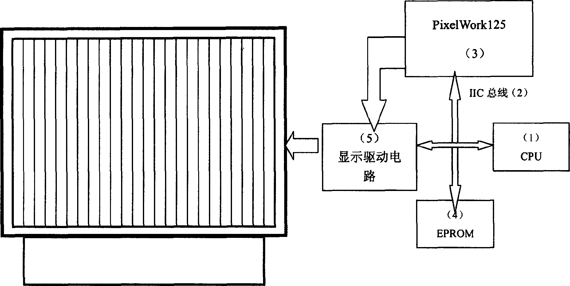
[0014] Such as figure 1 As shown, the microprocessor 1 of the digital light display rear projection transmits the control command to the decoding chip PixelWork125 through the IIC bus 2, reads the geometric debugging graphics stored in the EPROM, restores them into R, G, and B data, and inputs them to the display driver Circuit 5, projecting geometric debugging graphics on the TV screen. The IIC bus 2 is SDA signal and SCL signal.

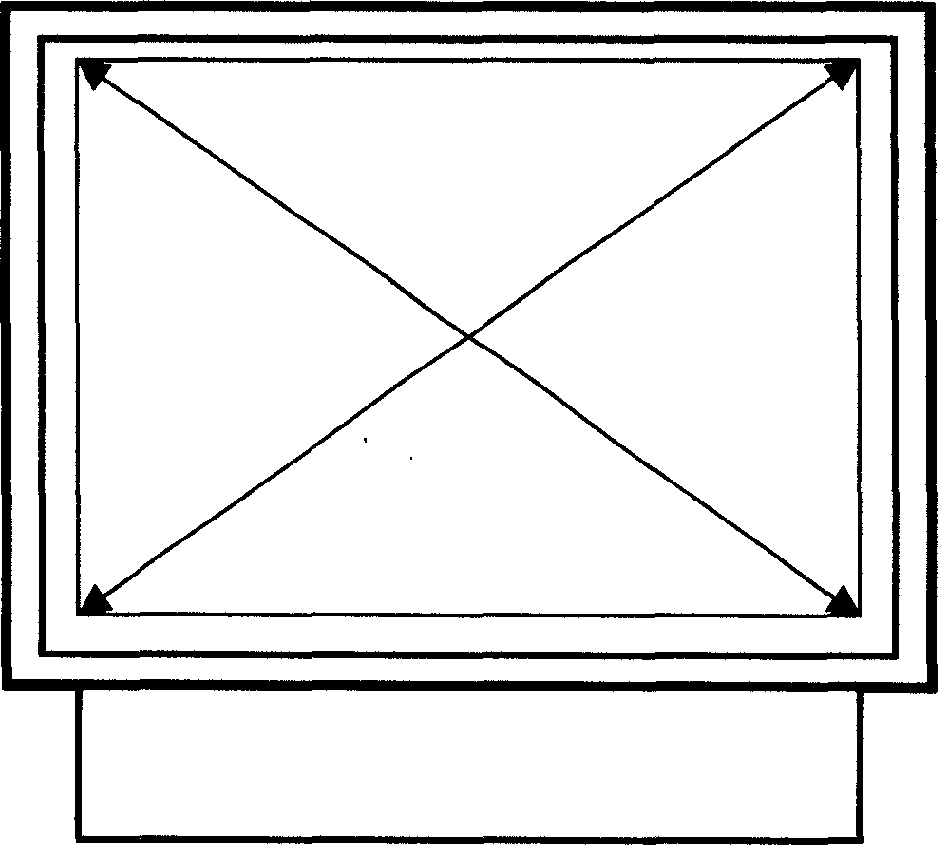
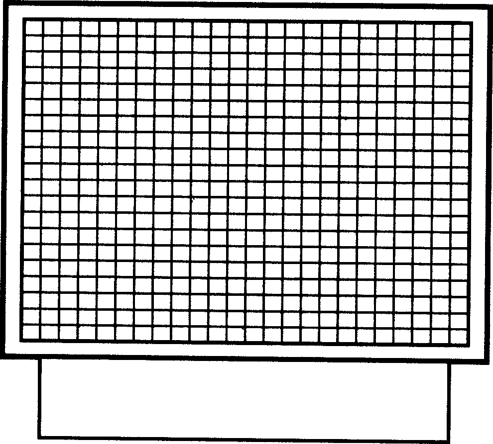
[0015] Such as figure 2 , image 3 As shown, when the digital light display rear projection is produced and assembled or after-sales maintenance, the geometric debugging graphics are called out through the OSD menu, and the optical distortion of the optical electromechanical engine is corrected according to the offset position of the geometric debugging graphics on the screen. figure 2 It is ...


PUM


Abstract

This invention discloses a ultra large screen digital optical-electro-mechanical engine optical distortion correction method, which contains solidifying standard test graphics in memory, in correcting the distortion, taking out graphics by OSD menu and projecting in digital the back projective screen, adjusting optical way reflection mechanism according to graphics.

Description

【Technical field】: [0001] The invention relates to a method for correcting optical distortion of a super-large-screen full-digital optical electromechanical engine. 【Background technique】: [0002] During the production and assembly of digital light display rear projection or after-sales maintenance, optical distortion needs to be corrected, so that the image projected on the screen is completely accurate and has no positional deviation. Optical distortion correction requires standard geometric graphics as a debugging signal. At present, the digital light display rear projection is connected to the geometric debugging graphics of the computer through the VGA input port as the optical distortion correction debugging signal. However, this method has great disadvantages , a computer with geometric debugging graphics software must be installed as a signal source to perform optical distortion correction and debugging, which brings great inconvenience to production assembly and af...

Claims


Application Information

Patent Timeline
IPC IPC(8): H04N5/74
Inventor 胡诗强陈绵锐朱国清姜新华
Owner SHENZHEN SKYWORTH RGB ELECTRONICS CO LTD
Learn More