Repeater for power line communication system

A power network and transmitter technology, applied in power line communication systems, distribution line transmission systems, systems using coupling circuits, etc., can solve problems such as low allowable transmission power

Inactive Publication Date: 2005-07-13
KONINKLIJKE PHILIPS ELECTRONICS NV
View PDF1 Cites 5 Cited by
  • Summary
  • Abstract
  • Description
  • Claims
  • Application Information

AI Technical Summary

Problems solved by technology

[0007] low allowabl

Method used


Image

  • Repeater for power line communication system
  • Repeater for power line communication system

Examples


Embodiment Construction

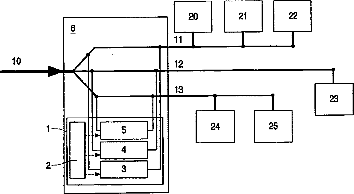
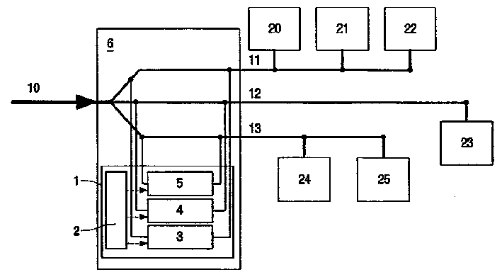
[0025] The upper part of the figure shows a home network based on power line communication in which different application devices 20 - 25 are connected to the three phases 11 , 12 and 13 of the power line 10 . These application devices can be, for example, a TV 20 on the first phase line 11, a video recorder 21 and a hard disk (HD) video recorder 22, a PC 23 on the second phase line 12, a Washing machines 24 and other applications 25 . In this type of configuration, communication problems between two application devices (such as a video recorder 21 and a PC 23 ) connected to different phase lines 11 , 12 may occur.

[0026] To solve this problem, according to the invention, a transponder 1 is connected to the phase lines 11, 12 and 13, wherein the transponder 1 is preferably installed in the central position of the meter box 6 or in an auxiliary distribution cabinet. However, the only important consideration is that the transponder 1 can be installed in a location where there...


PUM


Abstract

The invention relates to a method and a device (1) for data transmission in a power network (power line communication). The equipment (1) is preferably placed in a distribution cabinet (6), equipped with transceivers (3, 4, 5), each transceiver connected to a phase line (11, 12, 13) of the power network, from the transceiver Data can be received on the device, and data can be sent through them. The transceivers are coupled via a control unit (2), wherein the control unit ensures that data received on one phase line is prepared for transmission on at least one other phase line. Accordingly, retransmissions to all phase lines with the same transmission power, or retransmissions matching special signal strengths or data visited addresses can be realized.

Description

technical field [0001] The invention relates to a method and a device for data transmission in a power network. Background technique [0002] "Power Line Communication" (PLC) refers to a known method by which data is transmitted over the wires of a power network intended to supply electricity. The advantage of this type of power line communication lies primarily in the fact that, in more or less every home, lines belonging to the power grid are present in practically every room. This makes it possible to interconnect applications in different rooms without rewiring. At the same time, in this respect, signal transmission over power lines has hitherto only been permitted in a small frequency range according to obsolete statutory regulations, and these limits will be exceeded in the future, making data rates of more than 10 Mbit / s possible. Here, power line communication can be used not only as a main means of accessing the so-called "last mile" to the Internet through a powe...

Claims


Application Information

Patent Timeline
IPC IPC(8): H04B3/54H04L12/28H04L12/46H04L12/66H04L29/06
CPCH04B3/54H04B2203/5425H04B2203/5466H04B2203/5479H04B2203/5483H04L12/2838H04L12/4625H04L2012/2843H04L69/16H04L69/169H04L69/085H04L69/08H04L9/40
Inventor T·沃尔梅T·德鲍姆C·德佩
Owner KONINKLIJKE PHILIPS ELECTRONICS NV
Why Eureka
Try Eureka