Grid driving method and circuit of liquid crystal displaying device

A liquid crystal display and gate drive technology, applied in static indicators, instruments, etc., can solve the problems of different voltage levels, limited effect, unable to change the influence of scanning lines, etc., to increase the charging time and improve the effect of flickering problems

Active Publication Date: 2005-07-27
AU OPTRONICS CORP
View PDF0 Cites 19 Cited by
  • Summary
  • Abstract
  • Description
  • Claims
  • Application Information

AI Technical Summary

Problems solved by technology

But in fact, due to other factors such as the process, the feedthrough voltage effect of each liquid crystal sub-pixel will be different, so that the effect is limited
As shown in Figures 3A, 3B, 3C and formula (1), the voltage difference ΔV at the end of the starting signal waveform at the front and rear ends of the same scanning line is different, and the highest level V after waveform distortion 1 less than the highest level V of the start signal waveform GH , that is, the difference between the highest level and the lowest level of the start signal at the rear end of the scan line ΔV 1 Less than the difference ΔV between the highest level and the lowest level of the start signal at the front end of the scan line GH , causing the feedthrough voltage V generated at the front end of the scan line feedthrough and the rear-end generated feedthrough voltage V feedthrough are not equal, then adjust the common voltage V com It is also impossible to make the voltage on the liquid crystal capacitors at the front and rear ends of the same scan line relative to the common voltage V com The pressure difference between them is the same, so that the problem of screen flickering cannot be effectively solved
[0014] Different from the second way to solve the screen flickering above, in order to reduce the effect of the feed-through voltage, a waveform with a chamfering function can be used, such as Figure 6A As shown, this function makes the voltage difference ΔV at the end of the start signal waveform changed from the difference between the highest level and the lowest level ΔV GH becomes the new difference between the highest level and the lowest level ΔV' GH , because the voltage difference ΔV at the end of the starting signal waveform becomes smaller, so the feedthrough voltage effect also becomes smaller, but this method still cannot change the influence of the waveform distortion caused by the RC delay of the scan line, such as Figure 6B As shown, because of the RC delay, the waveform at the rear end of the scan line will rise relatively slowly, resulting in a different voltage level when the corner cutting function is activated, that is to say, the highest level V GH Will be greater than the highest level V after waveform distortion 2 , so the level after shaving is different, that is, the difference between the new highest level and the lowest level ΔV′ GH Will be greater than the difference ΔV′ between the new highest level and the lowest level after waveform distortion 2 , so by Figure 6A , 6B It can be seen that although the feed-through voltage effect is reduced, the common voltage V at both ends of the scan line com The pressure difference is still different, so it still cannot effectively solve the problem of screen flickering

Method used


Image

  • Grid driving method and circuit of liquid crystal displaying device
  • Grid driving method and circuit of liquid crystal displaying device
  • Grid driving method and circuit of liquid crystal displaying device

Examples


Embodiment Construction

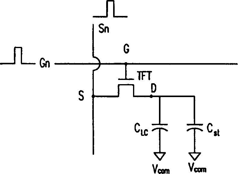
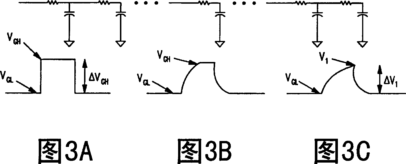
[0041] The technical feature of the present invention is to minimize the difference of the feed-through voltage of each transistor on the same scanning line, so as to reduce the screen flicker phenomenon. C in the present invention assumes formula (1) GD / (C GD +C LC +C st ) is a fixed value, focusing on the part of adjusting ΔV, that is, adjusting the pressure difference at the end of the start signal waveform.

[0042] Because the input positive voltage square wave signal (gate drive signal) will cause the above-mentioned known problems, the negative voltage square wave signal will also suffer the same effect when passing through the stray capacitance and resistance on the scanning line. Therefore, if a negative voltage square wave signal (correction signal) is superimposed on the positive voltage square wave signal to generate a modified gate drive signal, then only the front and rear end voltages of the scanning line generated when the positive voltage square wave signa...


PUM


Abstract

A driving method of grid on liquid crystal display includes generating signal for driving grid, superimposing revision signal in opposite polarity to driving signal of grid on grid driving signal for generating revised driving signal of grid in order to lower high potential level of grid driving signal and output the revised signal, utilizing this revised grid driving signal to drive corresponding scanning line.

Description

technical field [0001] The invention relates to an improvement method of a liquid crystal display, and in particular to a method for reducing flickering of the liquid crystal display screen and increasing charging time. Background technique [0002] Liquid crystal displays have become more and more popular in recent years, not only can save space, but also can reduce power consumption, now gradually large-scale, high-resolution liquid crystal displays are used to replace traditional displays, just like cathode ray tube displays (CRT display ), however, there is an important problem in large-size liquid crystal displays, that is, the larger the screen size of the liquid crystal display, the more serious the problem of flickering on the liquid crystal display screen. [0003] figure 1 It is the basic structure of a liquid crystal display (Liquid Crystal Display, LCD). The gate driver (Gate driver) 102 is responsible for turning on and off the thin film transistor (Thin Film T...

Claims


Application Information

Patent Timeline
Patent Type & Authority Applications(China)
IPC IPC(8): G02F1/133G09G3/36
Inventor 许文法易建宇
Owner AU OPTRONICS CORP
Why Eureka
Try Eureka