Magnetic resistant electric motor with double stator switch

A switched reluctance motor, double stator technology, applied in electrical components, electromechanical devices, magnetic circuit shape/style/structure, etc., can solve the problems of large torque ripple, small number of teeth, application limitations, etc., to achieve low torque ripple Effect

Inactive Publication Date: 2005-07-27
NANJING UNIV OF AERONAUTICS & ASTRONAUTICS
View PDF0 Cites 44 Cited by
  • Summary
  • Abstract
  • Description
  • Claims
  • Application Information

AI Technical Summary

Problems solved by technology

Since the stator and rotor of the switched reluctance motor are salient pole cogging structures, and the number of teeth is small, the cog

Method used


Image

  • Magnetic resistant electric motor with double stator switch
  • Magnetic resistant electric motor with double stator switch
  • Magnetic resistant electric motor with double stator switch

Examples


Embodiment Construction

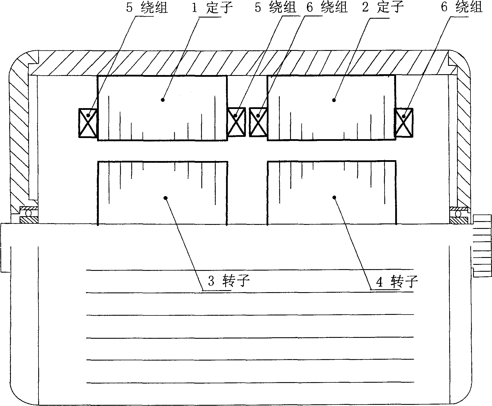
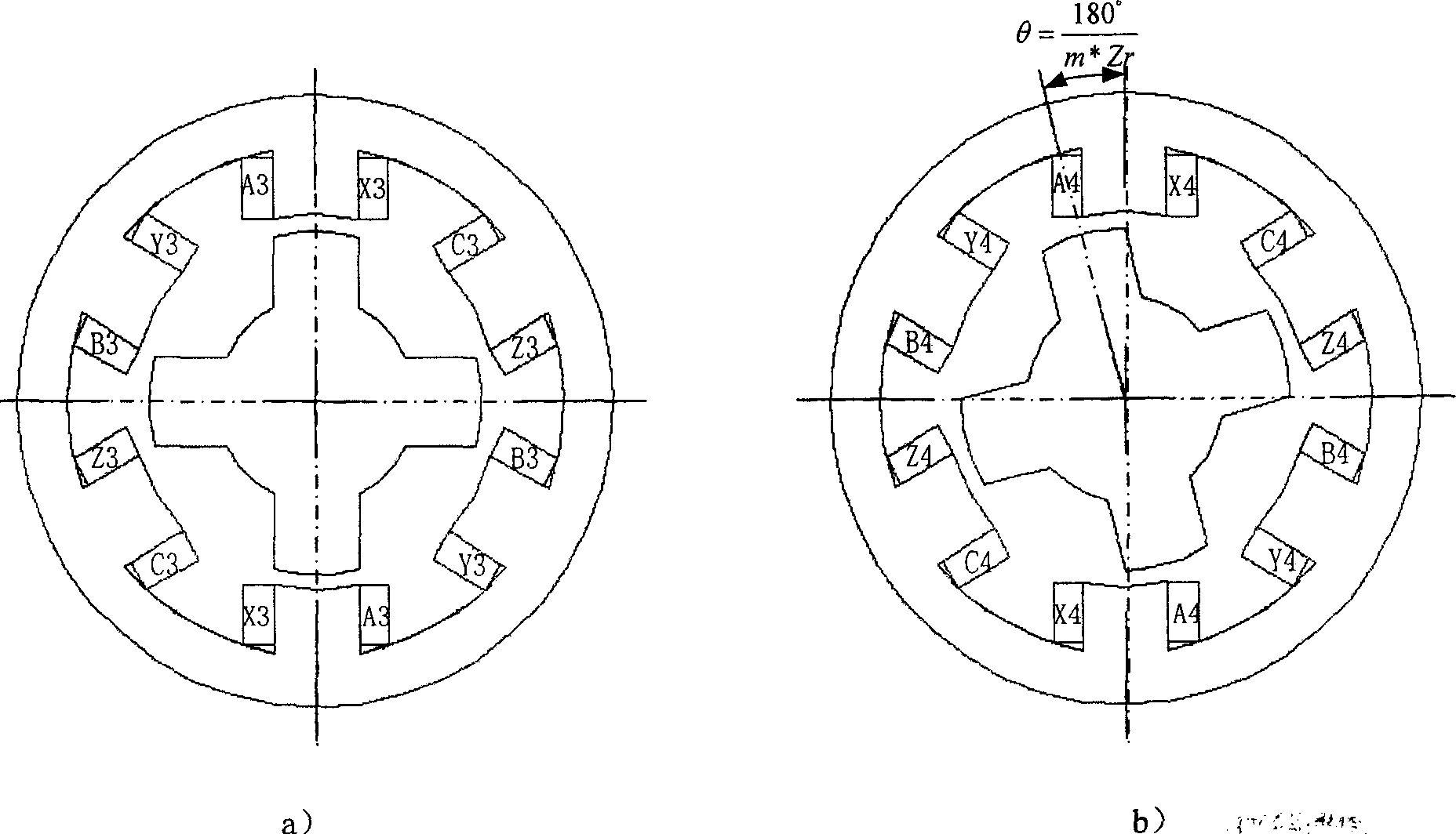
[0022] Since the working principles of the double-stator switched reluctance motors with different phases are similar, the structure of the present invention and the principle of reducing torque ripple will be described below by taking the three-phase 6 / 4 structure double-stator switched reluctance motor as an example.

[0023] The stator and rotor iron cores of the double-stator switched reluctance motor of the present invention are composed of two sections, and the lengths of the two iron cores are the same. As shown in Figure 1 and Figure 2, it is a structural schematic diagram of a three-phase 6 / 4 structure double-stator switched reluctance motor . The stators 1, 2 and the rotors 3, 4 are all made of laminated silicon steel sheets, and have a salient pole slot structure. The three-phase motor has a 6N / 4N (N is a positive integer 1, 2, 3, 4...) structure, that is, the number of stator teeth is 6N, and the number of rotor teeth is 4N. For example, if N=1, it is a three-phas...


PUM


Abstract

The invention consists of stator and rotator that both have salient pole type tooth socket structure made by pressed stack silicon steel sheet. The iron core of rotator and stator is composed of two stage iron cores having same length. The two stage iron cores of rotator or stator are installed by staggering 180/phase number degree electrical degree. The two groups of centralizing armature winding are separately sleeved on the stator tooth. The armature winding sleeved in two neighboring teeth having same phase is series connected or parallel connected to form one phase. The generated torque ripple is the combination of torque ripple generated from left side of motor and torque ripple generated from right side, so that combination of torque ripple can be increased and frequency can be increased one time.

Description

technical field [0001] The double-stator switched reluctance motor of the present invention belongs to the brushless DC motor of the motor class. Background technique [0002] Switched reluctance motor is one of the motors with the simplest structure and has broad application prospects. According to the number of phases, the motor can be divided into: (1) single-phase switched reluctance motor; (2) two-phase switched reluctance motor; (3) three-phase switched reluctance motor; (4) four-phase switched reluctance motor; ( 5) Multi-phase switched reluctance motor. Among them, the three-phase 6 / 4 structure and the four-phase 8 / 6 structure are widely used. Its traditional torque control strategies are: (1) current chopping control; (2) angle position control. Since the stator and rotor of switched reluctance motors are salient pole cogging structures, and the number of teeth is small, the cogging effect is obvious. The existing switched reluctance motors have the disadvantage ...

Claims


Application Information

Patent Timeline
IPC IPC(8): H02K1/06H02K3/28H02K16/04H02K29/06
Inventor 朱德明严仰光孟小利
Owner NANJING UNIV OF AERONAUTICS & ASTRONAUTICS
Why Eureka
Try Eureka