Plasma display apparatus

A display device, plasma technology, applied to static indicators, instruments, etc., can solve problems such as time-consuming

Inactive Publication Date: 2005-07-27
KONINKLIJKE PHILIPS ELECTRONICS NV
View PDF3 Cites 0 Cited by
  • Summary
  • Abstract
  • Description
  • Claims
  • Application Information

AI Technical Summary

Problems solved by technology

However, there will be some time between the instant when the hypotenuse of the pulse occurs and the subsequent instant when the plasma is excited

Method used


Image

  • Plasma display apparatus
  • Plasma display apparatus
  • Plasma display apparatus

Examples


Embodiment Construction

[0033] In different figures, the same reference numerals designate the same elements performing the same function.

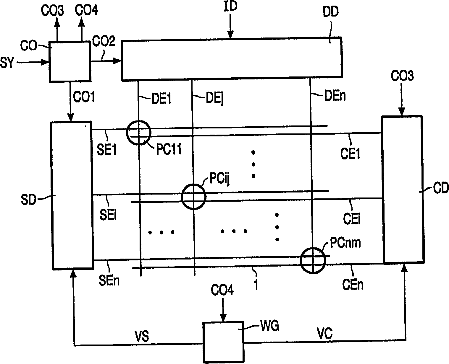
[0034] attachedfigure 1 It is a block diagram of the plasma display device.

[0035] The plasma display device includes a plasma display panel 1, a data driver DD, a scan driver SD, a common electrode driver CD, a controller CO and a waveform generator WG.

[0036] The known three-electrode plasma display panel 1 includes: scanning electrodes SE1 to SEn, also denoted as SEi; common electrodes CE1 to CEn, also denoted as CEi; data electrodes DE1 to DEm, also denoted as DEj; and plasma cells PC11 to PCnm, Also denoted as PCij.

[0037] The scan electrodes SEi and the common electrodes CEi are substantially arranged in parallel. Adjacent scan electrodes SEi and common electrodes CEi are connected to the same plasma cell PCij. Usually, the plasma cells PCij are not physically independent, but are multiple regions in the plasma channel. The plasma channel is conn...


PUM


Abstract

A plasma display apparatus comprises a waveform generator (WG) coupled between first and the second electrodes (SEl, CEl) to supply, across plasma cells (PCij), a sustain voltage (VCP) with slopes comprising a main part (MA) and a minor part (MI) succeeding the main part (MA). The main part has a duration longer than a formative time 5 lag (FTL) of the plasma cells (PCij), and the minor part has a smaller amplitude than the main part (MA). The plasma cells (pCij) are ignited and sustained by the minor part (MI). The main part (MA) has less steep slopes than the prior-art waveform. Consequently, the EMI produced by the main part (MA) will be at a lower frequency. The minor part (MI) has an amplitude which is relatively low and thus does not add considerably to the EMI, even 10 when its slopes are relatively steep. As the plasma is neither ignited nor sustained by the main part (MA), the main part (MA) further has a lower amplitude than the slope of the prior art and thus produces less EMI.

Description

technical field [0001] The invention relates to a plasma display device. Background technique [0002] During the sustain phase of a plasma panel having a matrix of plasma cells, a driver must provide an alternating voltage between the electrodes of the plasma panel to generate light in the plasma cells that are ready to emit light. In principle, it is possible to drive a plasma panel with a square wave voltage. However, when the voltage across the capacitor reverses polarity, a large charge or discharge current will flow. These large currents are caused by the large plasma panel capacitance that exists between the electrodes and the steep slope of the AC square wave voltage. [0003] As disclosed in EP-A-0548051 or EP-A-0704834, the driver includes an energy recovery circuit in which an inductor and a capacitor form a resonant circuit to reduce energy loss and The amount of EMI (electromagnetic interference). In the resonant circuit, the voltage across the capacitor rev...

Claims


Application Information

Patent Timeline
IPC IPC(8): G09G3/20G09G3/296
CPCG09G3/2965G09G2330/06G09G3/296
Inventor A·H·M·霍特斯拉格M·H·克莱恩D·A·科特F·沃斯森
Owner KONINKLIJKE PHILIPS ELECTRONICS NV
Why Eureka
Try Eureka