Tire noise reducing system

A tire and noise technology, applied in the field of tire noise reduction system, can solve problems such as harshness and increased sound

Active Publication Date: 2005-08-03
SUMITOMO RUBBER IND LTD
View PDF0 Cites 17 Cited by
  • Summary
  • Abstract
  • Description
  • Claims
  • Application Information

AI Technical Summary

Problems solved by technology

[0004] However, if air resonance is effectively reduced, another type of sound is correspondingly amplified and becomes harsh

Method used


Image

  • Tire noise reducing system
  • Tire noise reducing system
  • Tire noise reducing system

Examples


Embodiment Construction

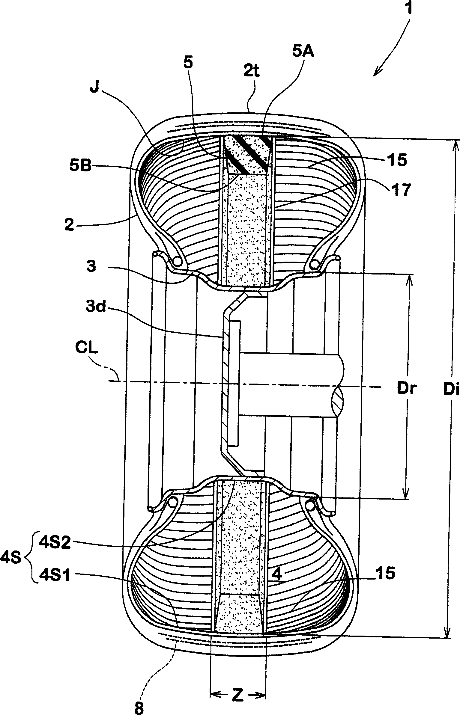
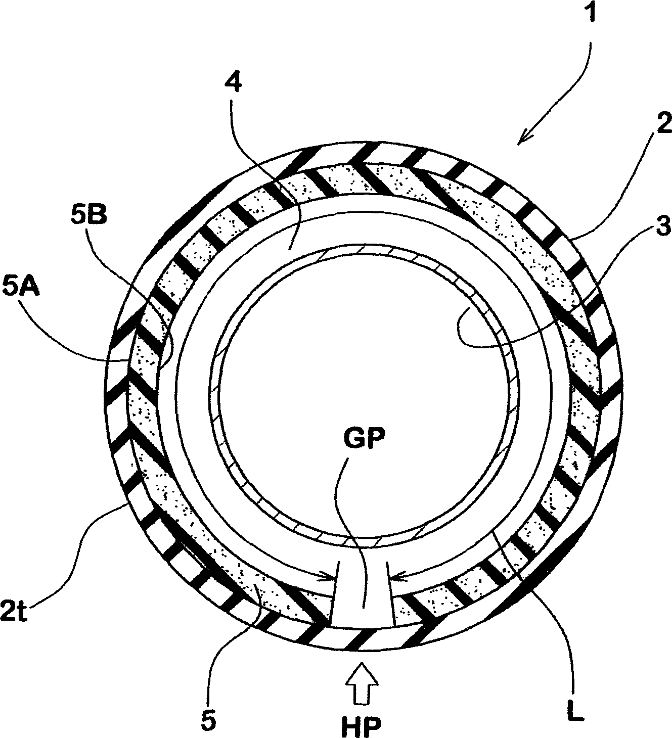
[0030] According to the invention, a muffler 5 is arranged in the cavity 4 of the assembly pneumatic tire 2 and rim 3 .

[0031] The pneumatic tire 2 has a tread portion 2t, a pair of sidewall portions 2s, and a pair of axially spaced bead portions 2b, thereby having a toroidal and annular tire hollow.

[0032] The rim 3 includes a pair of bead seats 3b for the beads 2b, a pair of flanges 3f extending radially outward from the bead seats 3b, and a bead seat located between the bead seats 3b. Between the rim well (rim well) 3w for tire installation.

[0033] When the tire hollow is closed by the rim, the rim 3 and the tire 2 mounted thereon form an annular cavity 4 . Here, the cavity surface 4s is defined as the surface facing said cavity 4, ie, the inner surface 4s1 of the tire and the inner surface 4s2 of the rim.

[0034] In this embodiment, the tire 2 is a radial tire for passenger cars. The rim 3 may be a specially designed rim, but in this embodiment a standard rim is ...


PUM

PropertyMeasurementUnit
hardnessaaaaaaaaaa
hardnessaaaaaaaaaa
hardnessaaaaaaaaaa

Abstract

A tire noise reducing system comprises a pneumatic tire (2) with a hollow, a wheel rim (3) on which the tire is mounted so that said hollow forms a closed cavity (4), and a noise damper (5) disposed in the closed cavity, wherein the noise damper is formed by fixing a strip of a porous material to the tire or wheel rim, the noise damper (5) has a volume in a range of from 0.4 to 20 % of the volume of the cavity (4), the noise damper has a sectional shape substantially constant in the tire circumferential direction, and the pneumatic tire comprises a tread portion (2t) provided with tread grooves (G1-G4) defining a tread pattern having a sea ratio of 20 to 35 %.

Description

technical field [0001] The present invention relates to a tire noise reduction system, and more particularly, to a pneumatic tire suitable for use in combination with a muffler disposed in a tire cavity. Background technique [0002] The noise produced by tires rolling on the road is divided into many sound types according to their cause and sound source. For example, the so-called road noise, which sounds like "GHO", caused by the resonance of the air in the annular tire cavity, has a maximum power spectrum ranging from about 100 Hz to 250 Hz. [0003] Sound absorbers made of spongy material disposed in the tire cavity are well known in the field of tires. This spongy material arranged in the tire cavity can suppress the air resonance. [0004] However, if the air resonance is effectively reduced, another type of sound is correspondingly increased and becomes harsh. In particular, the so-called pattern pitch noise of about 200 Hz and the so-called "SHAH" sound of more th...

Claims


Application Information

Patent Timeline
Patent Type & Authority Applications(China)
IPC IPC(8): B60C5/00B60C9/20B60C11/00B60C11/03B60C15/06B60C19/00
CPCB29D30/0654B29D2030/0655B60C11/0318B60C19/002B60C11/033Y10T152/10783Y10T152/10495Y10T152/10765
Inventor 汤川直树松本忠雄
Owner SUMITOMO RUBBER IND LTD
Why Eureka
Try Eureka