High light gain penetration reflective plate of liquid crystal display and its producing process

A liquid crystal display and reflector technology, which is applied in the field of penetrating reflectors, can solve the problems that the backlight cannot be fully utilized, the light transmission area cannot be too large, and the backlight is wasted.

Inactive Publication Date: 2005-08-03
WISTRON OPTRONICS CORP
View PDF0 Cites 2 Cited by
  • Summary
  • Abstract
  • Description
  • Claims
  • Application Information

AI Technical Summary

Problems solved by technology

In order to provide two display modes of reflection and transmission, the transflective LCD contains a transflector (transflector). For example, FIG. Light zone 12b, reflective zone 12a reflects the light on the front side, and light-transmitting zone 12b then allows the light on the rear side to pass through. However, this device 12 causes an insurmountable problem. Blocking, only the backlight

Method used


Image

  • High light gain penetration reflective plate of liquid crystal display and its producing process
  • High light gain penetration reflective plate of liquid crystal display and its producing process
  • High light gain penetration reflective plate of liquid crystal display and its producing process

Examples


Embodiment Construction

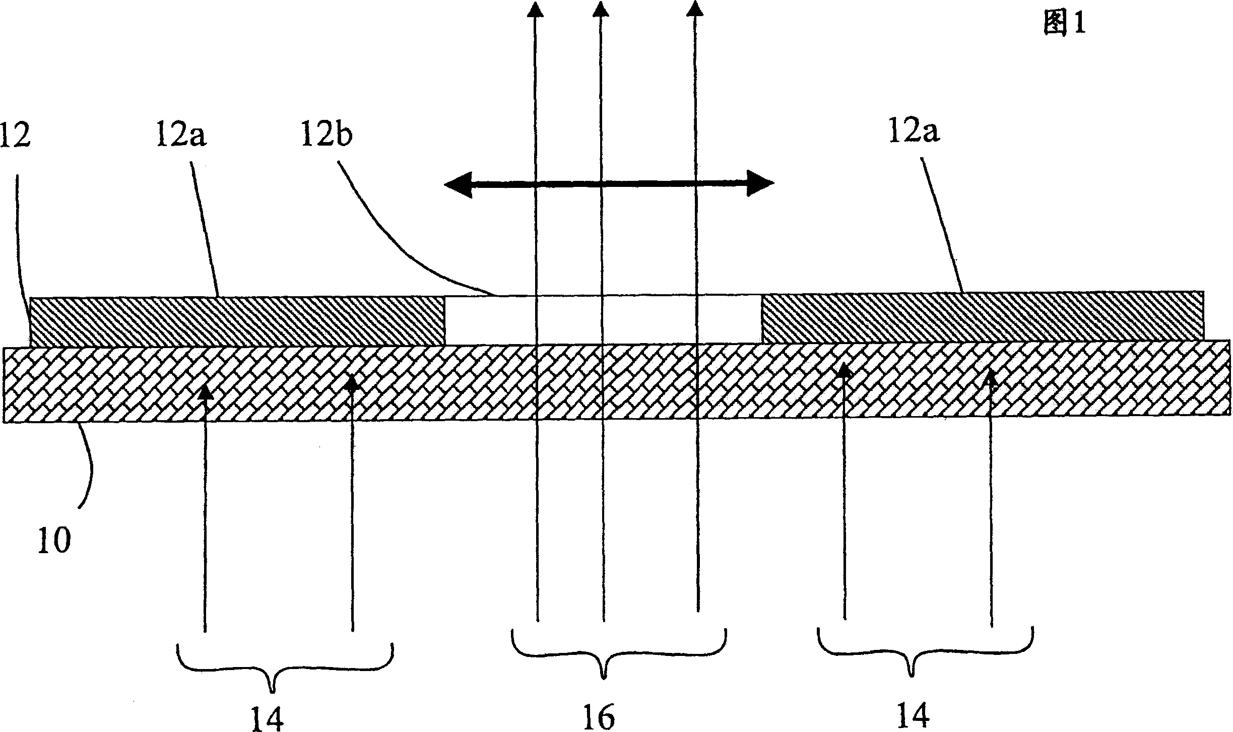
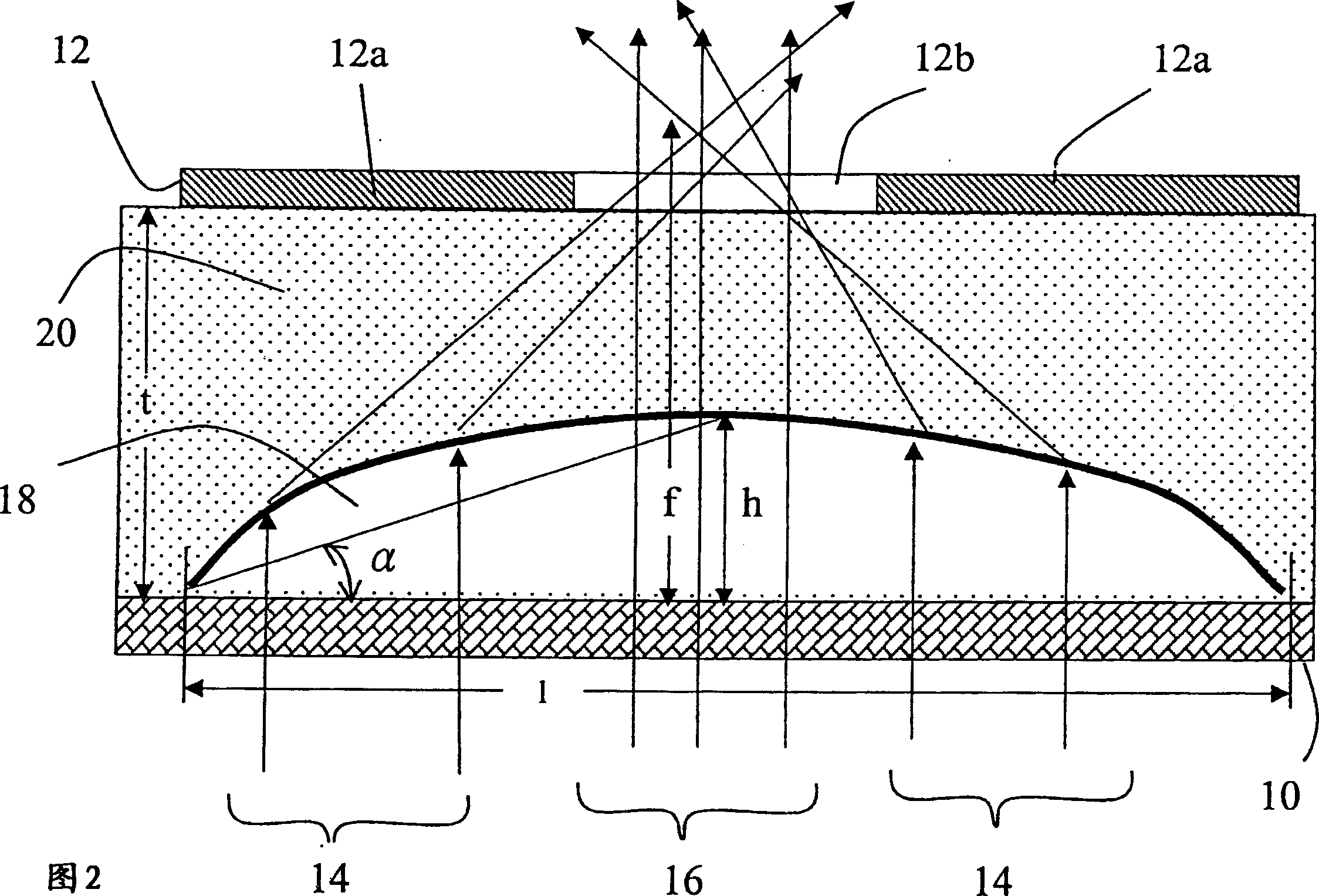
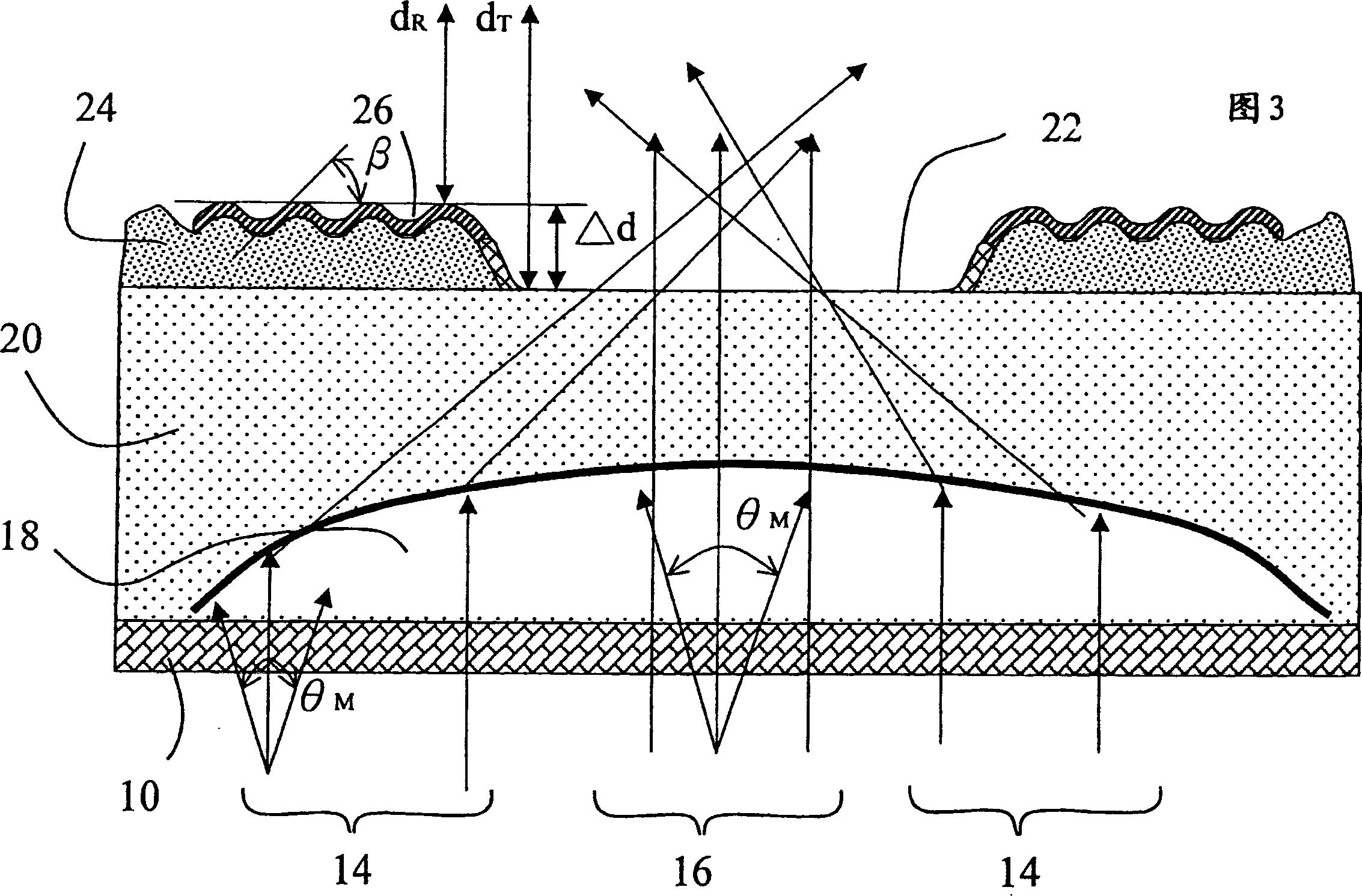
[0064] Fig. 2 is a schematic diagram of the first embodiment of the present invention. Between the substrate 10 and the transflector 12 are arranged microlenses 18 covered with an over coating 20 . The refractive index n of the microlens 18 L 1.4-2.5, the refractive index n of the flat layer 20 C less than n L . The microlens 18 collects the backlights 14 and 16 and projects them to the light-transmitting region 12b, so that the backlight 14 that could not be directly projected to the light-transmitting region 12b is utilized to increase the light gain. The LCD is composed of an upper plate and a lower plate sandwiching a liquid crystal. Switching elements, such as thin film transistors (TFT) or diodes, are formed on the lower plate. There are also liquid crystals and upper plates, which are prior art and are not described in detail in the figure. The transflector 12 can be formed by metal deposition and etching. In the device shown in Fig. 2, the microlens 18 has a widt...


PUM

PropertyMeasurementUnit
Center heightaaaaaaaaaa
Thicknessaaaaaaaaaa
Center heightaaaaaaaaaa

Abstract

The high light gain penetrating and reflecting plate is for LCD comprising one lower plate, one upper plate and one sandwiched liquid crystal layer. The high light gain penetrating and reflecting plate is located in the side of the lower plate with switch element. The high light gain penetrating and reflecting plate includes one light penetrating area, one reflecting area and at least one micro lens, and the micro lens focuses light to the light penetrating area for high light gain.

Description

technical field [0001] This invention relates to liquid crystal displays (LCDs), and more particularly to transflective panels for LCDs. Background technique [0002] A reflective LCD displays images by reflecting light in the environment through a reflector. Therefore, when the light in the environment is weak, a clear display effect cannot be obtained. The transmissive LCD provides a backlight to overcome the lack of light. However, the backlight consumes power and is not conducive to reducing the size and weight of the LCD. The new display, transflective LCD, provides reflective and transmissive display modes. When the brightness of the environment is insufficient, the backlight provides enough light. Otherwise, the backlight is turned off to save power. In order to provide two display modes of reflection and transmission, the transflective LCD contains a transflector (transflector), for example, FIG. 1 is a typical transflector 12 on a transparent substrate 10, which in...

Claims


Application Information

Patent Timeline
IPC IPC(8): G02B5/08G02B5/23G02F1/1335G03F7/00
Inventor 刘鸿达
Owner WISTRON OPTRONICS CORP
Why Eureka
Try Eureka