Textile machinery

A technology of textile machinery and processing unit, applied in the structural field of textile machinery, can solve the problems of dirtying the package and reducing the quality of the package, and achieve the effect of improving the success rate, preventing the reduction of production efficiency and improving the workability

Active Publication Date: 2005-08-10
MURATA MASCH LTD
View PDF1 Cites 31 Cited by
  • Summary
  • Abstract
  • Description
  • Claims
  • Application Information

AI Technical Summary

Problems solved by technology

Therefore, in the frequent recycling operation of collecting full packages, the operator must go up and down the travel path of the rolling trolley every time.
Moreover, when the operator i

Method used


Image

  • Textile machinery
  • Textile machinery
  • Textile machinery

Examples


Embodiment Construction

[0033] The best embodiment of the present invention will be described below with reference to the accompanying drawings.

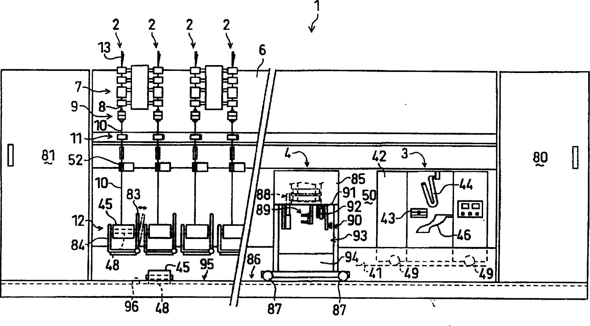
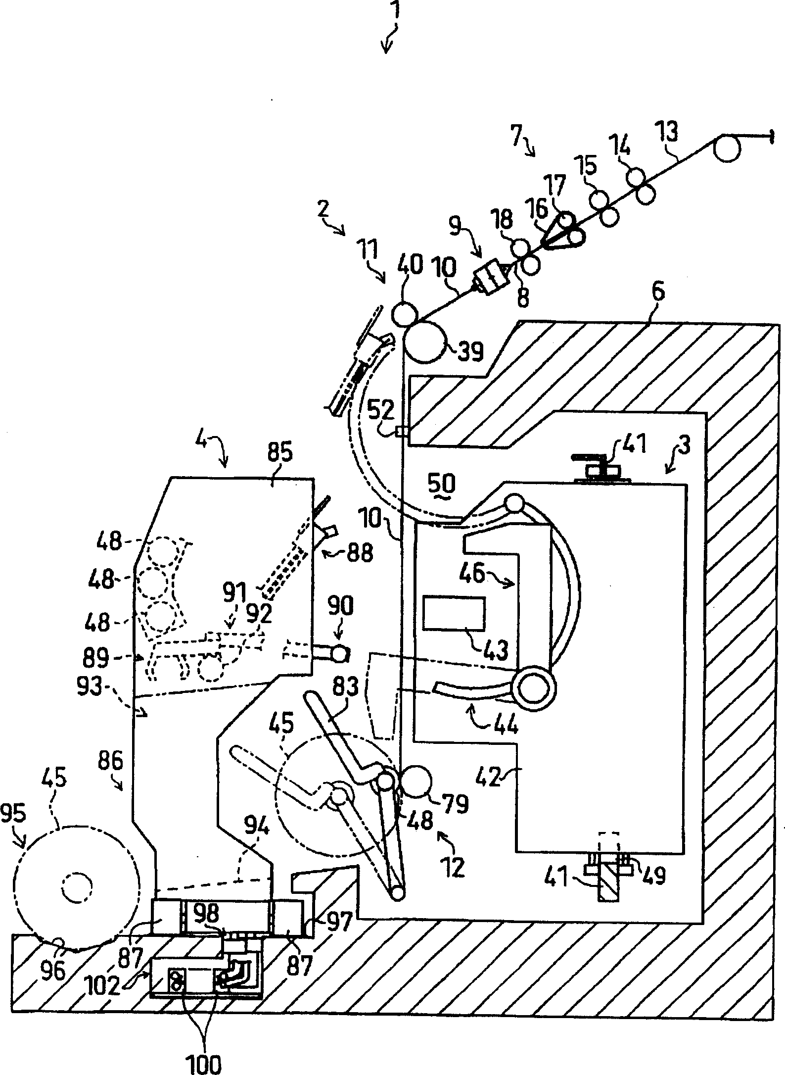
[0034] figure 1 A spinning machine 1 as a spinning machine including a plurality of spinning units (yarn processing units) 2 arranged in parallel is shown. The textile machine 1 includes a piecing cart 3 freely movable along the direction in which the spinning units 2 are arranged, a doffing cart 4 independently of the piecing cart 3 and freely movable, a blower cabinet 80 and a power cabinet 81 .

[0035] Such as figure 1 As shown, the main structures of each textile unit 2 include a traction device 7 , a textile component 9 , a yarn feeding device 11 and a winding device 12 . The pulling device 7 is arranged near the upper end of the casing 6 of the main body of the spinning machine 1, and is configured to spin the fiber bundle 8 delivered by the pulling device 7 by the spinning member 9. After passing through a yarn clearer (yarn defect detector) 5...


PUM


Abstract

To provide a textile machine enabling easy doffing of a full package 45. The textile machine 1 has a plurality of yarn-processing units 2 capable of forming a package 45 and placed in a row. The machine is provided with a doffing truck 4 traveling between the units along the direction of the yarn processing unit row and transferring the full package 45 to a storage area 95. The traveling path 86 of the doffing truck 4 is placed between the storage area 95 of the full package 45 and the yarn processing unit 2 in a direction perpendicular to the direction of the yarn processing unit row (the lateral direction in the selected figure). When the yarn running side of the yarn processing unit 2 is taken as the front side, the traveling path 86 of the doffing truck 4 and the storage area 95 are placed at the front side.

Description

technical field [0001] The present invention relates to a structure of a textile machine including a plurality of yarn processing units capable of forming a package. Background technique [0002] Patent Document 1 discloses a spinning machine in which a doffing device and a piecing device are installed on different carriages. In this textile machine, as in Patent Document 1 image 3 As shown, a loading area where fully wound packages are placed is provided between the spinning unit and the guide rail for the doffing device (travel path of the doffing cart). [0003] Patent Document 1: Japanese Patent Application Laid-Open No. 9-110301 (paragraph number 0013) [0004] However, since the structure of the above-mentioned Patent Document 1 is a layout in which the loading area of ​​the full package is arranged on the side close to the center of the textile machine, when the operator wants to collect the full package placed on the loading area, he needs to The recovery operatio...

Claims


Application Information

Patent Timeline
IPC IPC(8): B65H67/04D01H1/115D01H4/02D01H9/08D01H9/10D01H9/14D01H15/013
Inventor 井上敬目片努
Owner MURATA MASCH LTD
Why Eureka
Try Eureka