Magnetic recording medium , magnetic memory and method of producing magnetic recording medium
A magnetic recording medium and magnetic layer technology, applied in the direction of recording information storage, magnetic recording, information storage, etc., can solve the problems such as difficult to improve the recording magnetic field, rewriting performance of recording characteristics, and deterioration of nonlinear transition offset
- Summary
- Abstract
- Description
- Claims
- Application Information
AI Technical Summary
Problems solved by technology
Method used
Image

Examples
Embodiment I-V and comparative example C1-C5
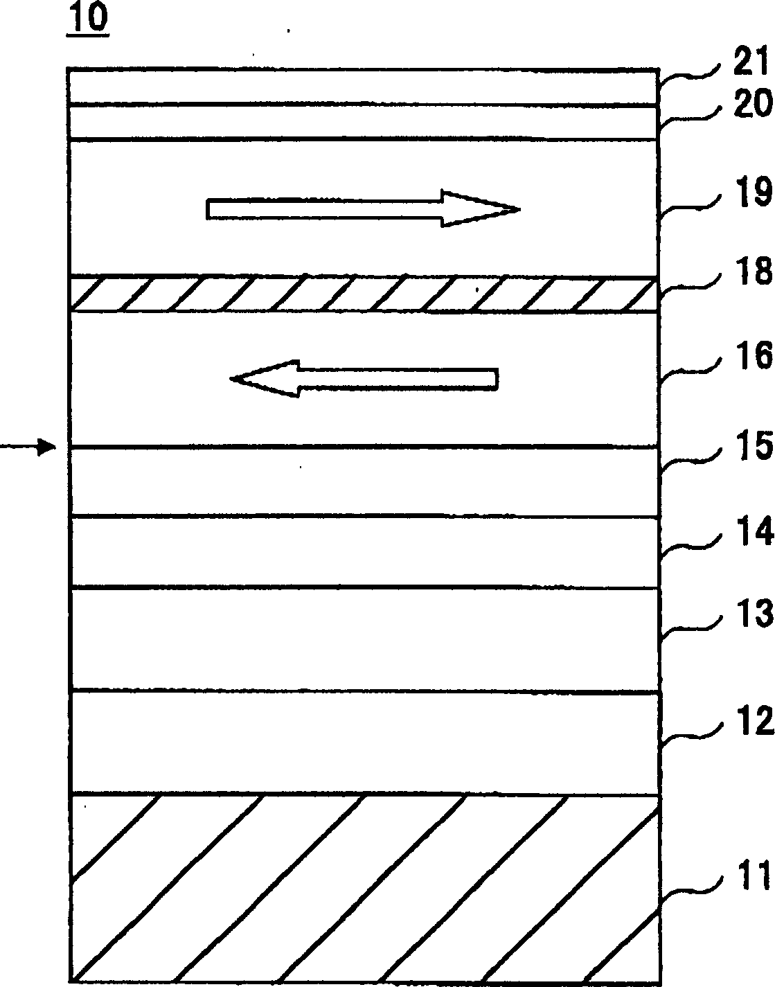
[0077] Disks of Examples I-V and Comparative Examples C1-C5 were prepared with the following stacked structures: textured textured glass substrate, 25 nm thick Cr 50 Ti 50 First seed layer, 10nm thick Al 50 Ru 50 Second seed layer, 3nm thick first underlayer, 3nm thick second underlayer, 2nm thick Co 90 Cr 10 First magnetic layer, 0.8nm thick Ru non-magnetic coupling layer, 16nm thick Co 60 Cr 18 Pt 11 B 8 Cu 3 Second magnetic layer, 5.5nm thick DLC protective layer and 1.5nm thick AM3001 lubricating layer.
[0078] Except for the AM3001 lubricating layer, each layer of the stack structure was formed by a DC magnetron sputtering device. Formation of Cr on textured glass substrates 50 Ti 50 Before the first seed layer, the inside of the DC magnetron sputtering device is evacuated to less than or equal to 4×10 -5 Pa, and the textured glass substrate was heated to 180°C. The pressure inside the DC magnetron was set at 0.67 Pa except when the DLC protective layer was ...
Embodiment I
[0084] Embodiment IV will Cr 92.5 W 7.5 For the second bottom layer 15, to replace the Cr used in embodiment 1 75 Mo 25 . When having Cr(N) first bottom layer 14 and Cr 92.5 W 7.5 Embodiment IV of the second bottom layer 15 and the first bottom layer with Cr and Cr 92.5 W 7.5 When comparing the comparative example C4 of the second bottom layer, the coercive force square ratio of the embodiment IV is improved by 0.09 compared with the coercive force square ratio of the comparative example C4, and the resolution of the embodiment IV is comparable to that of the comparative example C4. Ratio increased by 2.1%.
[0085] Example V will Cr 95 W 5 For the first bottom layer 14, Cr(N) in Example I is not used. When having Cr 95 W 5 1st bottom layer 14 and Cr 75 Mo 25 Embodiment V of the second bottom layer 15 is the same as having Cr 95 W 5 First bottom layer and Cr 75 Mo 25 When compared with the comparative example C5 of the second bottom layer, the coercive force ...
Embodiment VI and comparative example C6
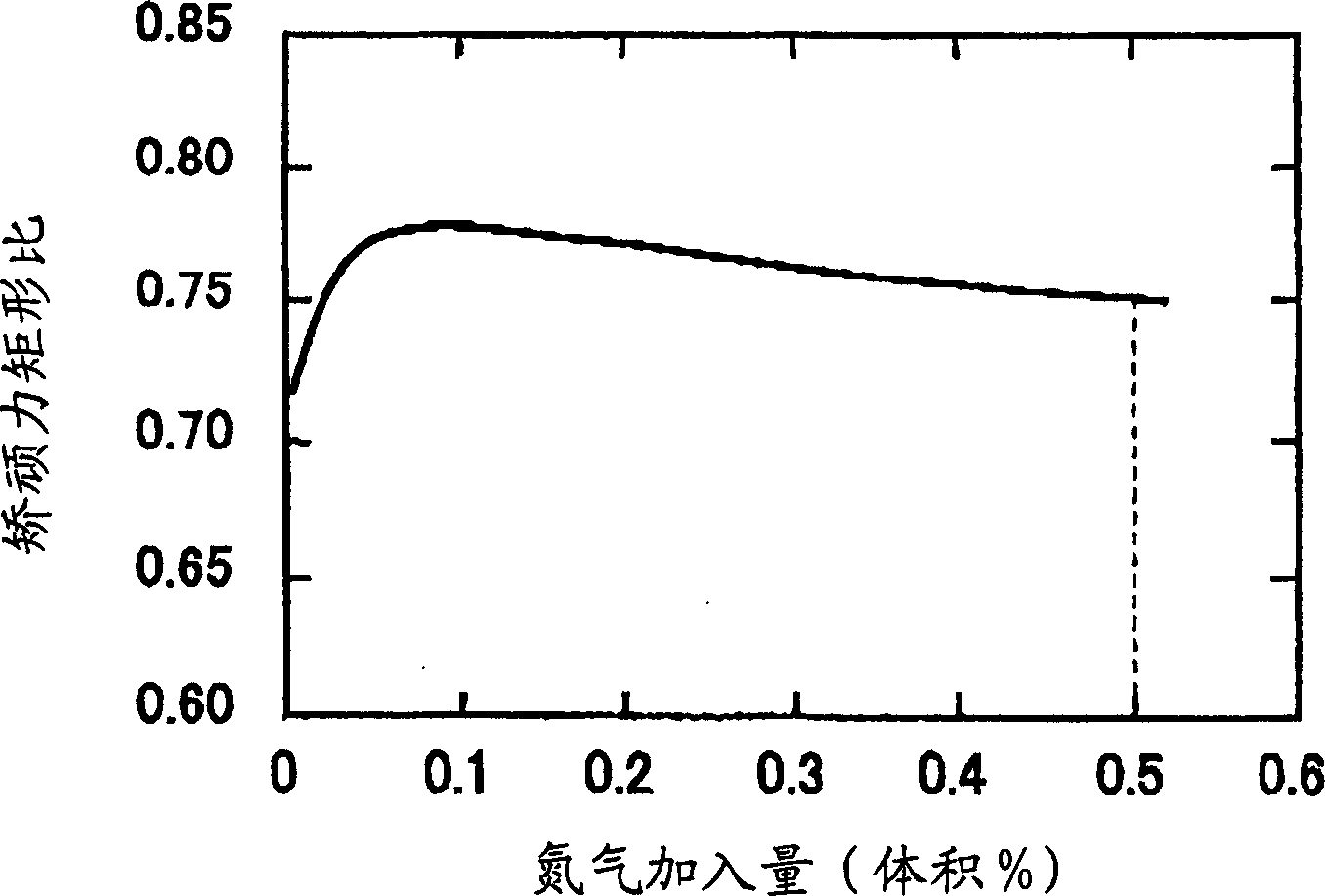
[0092] Below, will refer to Figures 3 to 9 The disk characteristics of Example VI are described. In Example VI, the amount of nitrogen gas added to the Ar gas atmosphere when the first underlayer 14 was formed was varied from 0 to 0.50 vol% in increments of 0.05 vol%. In addition, the formation of Cr in an Ar gas atmosphere without nitrogen addition 75 Mo 25 2nd bottom floor 15.
[0093] In Table 1, Comparative Example C6 corresponds to the case where the amount of nitrogen gas added to the Ar gas atmosphere was 0, that is, no nitrogen gas was added when forming the first underlayer. exist Figures 3 to 9 In each feature shown in , the eigenvalues are interpolated from the eigenvalues obtained in 0.05vol% increments.
[0094] The magnetic disks of Example VI and Comparative Example C6 are all made into the following stacked structure, and the stacked structure is composed as follows: textured textured glass substrate, 25nm thick Cr 50 Ti 50 First seed layer, 10nm t...
PUM
| Property | Measurement | Unit |
|---|---|---|
| Thickness | aaaaa | aaaaa |
| Thickness | aaaaa | aaaaa |
Abstract
Description
Claims
Application Information
 - R&D
- Intellectual Property
- Life Sciences
- Materials
- Tech Scout
- Unparalleled Data Quality
- Higher Quality Content
- 60% Fewer Hallucinations
Browse by: Latest US Patents, China's latest patents, Technical Efficacy Thesaurus, Application Domain, Technology Topic, Popular Technical Reports.
© 2025 PatSnap. All rights reserved.Legal|Privacy policy|Modern Slavery Act Transparency Statement|Sitemap|About US| Contact US: help@patsnap.com