

Light emitting element with metal base composite material carrier
A composite material and metal matrix technology, which is applied in the direction of electrical components, semiconductor devices, laser components, etc., can solve the problems of peeling off metal substrates and light-emitting laminates
- Summary
- Abstract
- Description
- Claims
- Application Information
AI Technical Summary
Problems solved by technology
Method used
Image

Examples
Embodiment Construction
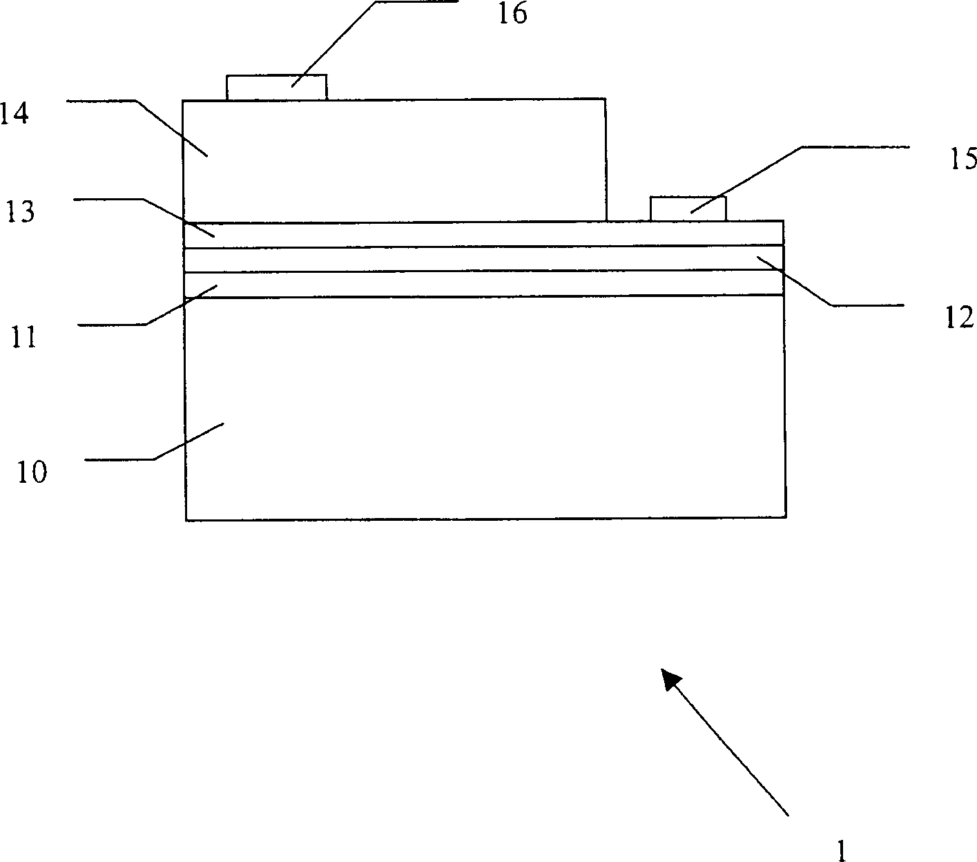
[0021] see figure 1 According to a preferred embodiment of the present invention 1, a light-emitting element 1 with a metal matrix composite material carrier includes a metal matrix composite material carrier 10, wherein the metal matrix composite material carrier is filled with a suitable metal matrix in a carrier with holes, The thermal expansion coefficient of the metal matrix composite material carrier is close to the thermal expansion coefficient of a luminescent laminate; a metal reflective layer 11 formed on the metal matrix composite material carrier; a transparent bonding layer 12 formed on the metal reflective layer; forming A transparent conductive layer 13 on the transparent adhesive layer, wherein the upper surface of the transparent conductive layer includes a first surface area and a second surface area; a light emitting stack 14 formed on the first surface area; a first wiring electrode 15 formed on the second surface area; and a second wiring electrode 16 form...
PUM
 Abstract
Description
Claims
Application Information