Low power consumption brushless DC motor with Halbach magnet structure

A DC motor, low power consumption technology, applied in the magnetic circuit shape/style/structure, magnetic circuit rotating parts, electrical components and other directions, which can solve the problems of low air gap magnetic density, large air gap, and reduced motor power density. , to achieve the effect of small armature reaction, small volume and improved motor torque

Inactive Publication Date: 2005-08-10
BEIHANG UNIV
View PDF0 Cites 21 Cited by
  • Summary
  • Abstract
  • Description
  • Claims
  • Application Information

AI Technical Summary

Problems solved by technology

Cogging brushless DC motors can eliminate cogging torque and tooth harmonics, but due to the large effective

Method used


Image

  • Low power consumption brushless DC motor with Halbach magnet structure
  • Low power consumption brushless DC motor with Halbach magnet structure
  • Low power consumption brushless DC motor with Halbach magnet structure

Examples


Embodiment Construction

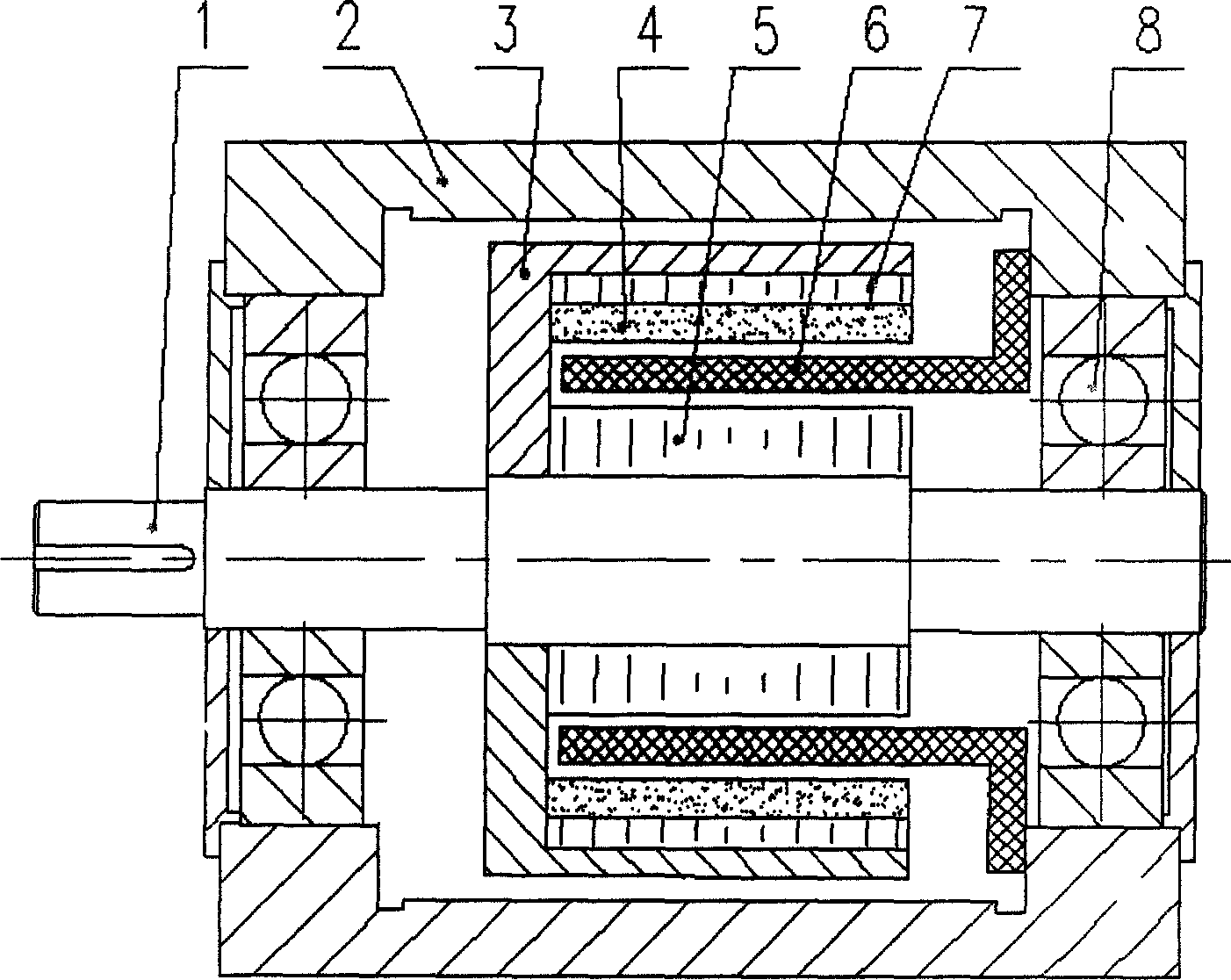
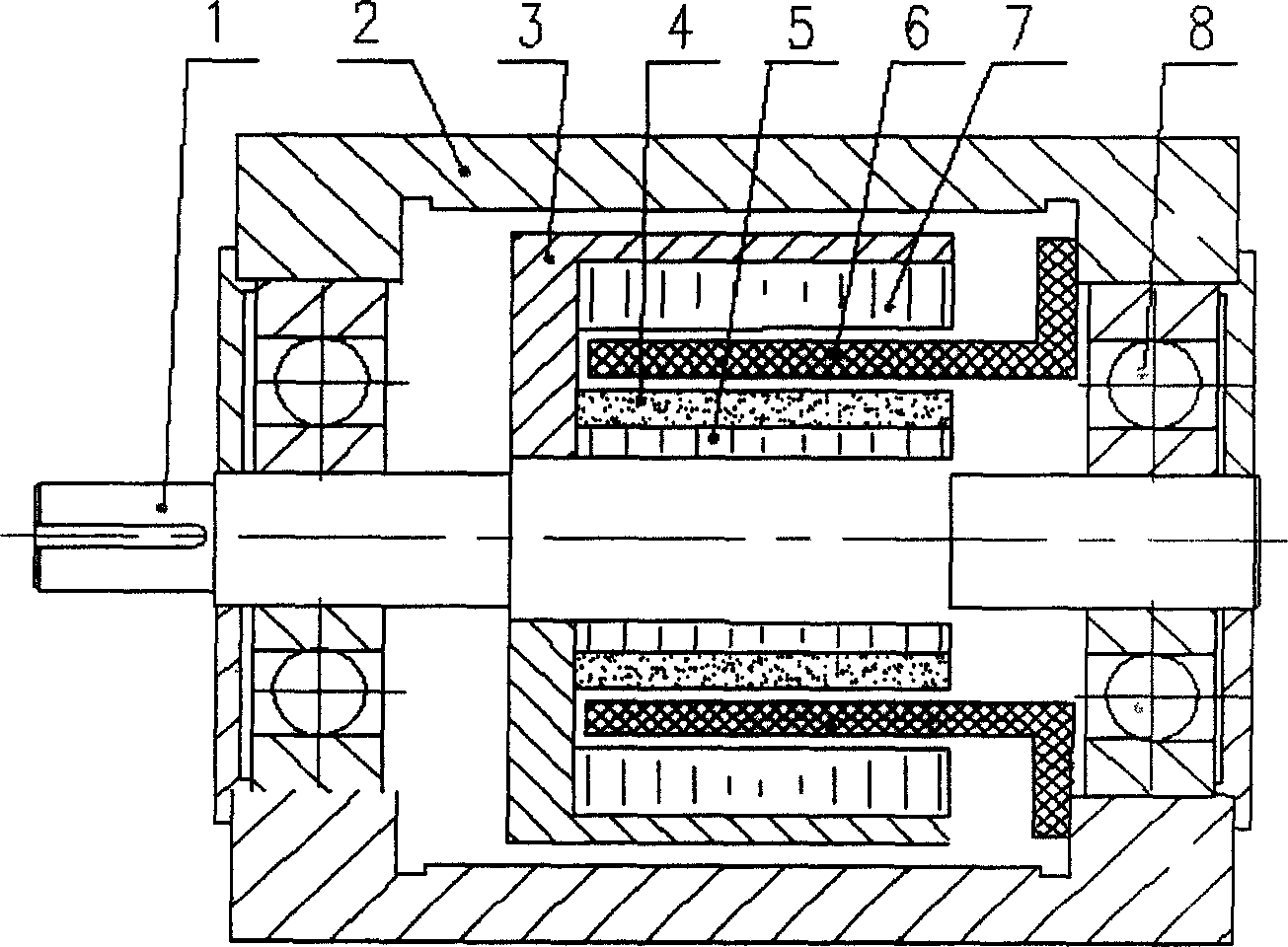
[0011] like figure 1 and figure 2 As shown, the brushless DC motor of Halbach magnet structure of the present invention is made up of rotor shaft 1, casing 2, sleeve 3, Halbach magnet 4, inner rotor iron core 5, hollow cup stator 6, outer rotor iron core 7 and bearing 8, The outer rotor core 7 and the inner rotor core 5 are connected to the rotor shaft 1 through the sleeve 3, so that the outer rotor core 7 and the inner rotor core 5 rotate together with the rotor shaft 1, and the Halbach magnet 4 can be installed on the inner rotor core 5, such as figure 1 As shown, it can also be installed on the outer rotor core 7, such as figure 2 As shown, considering that the rotor will generate a huge centrifugal force when it rotates at a high speed, the Halbach magnet 4 is generally placed on the outer rotor core 7 .

[0012] When the rotor shaft 1 and the sleeve 3 are made of magnetically conductive materials, both the outer rotor core 7 and the inner rotor core 5 need to be fixed...


PUM


Abstract

The disclosed DC motor includes following parts mainly: iron core of external rotor, air core cup type stator (including windings and framework), Halbach magnet, iron core of inner rotor, and rotor shaft. Iron core of external rotor and iron core of inner rotor are connected to rotor shaft so as to rotate together. Halbach magnet is installed on iron core of inner rotor or iron core of external rotor. Air core cup type stator is fixed on body case. Permanent magnetic circuit passing through Halbach magnet, iron core of rotor and their air gap constitutes a closed loop. Advantages of the invention are: reducing thickness of iron core and increasing magnetic density of air gap greatly by using new type structure of Halbach magnet so as to decrease size and weight and lower wastage of motor.

Description

Technical field [0001] The invention relates to a permanent magnet brushless direct current motor, in particular to a Halbach magnet structure low power consumption brushless direct current motor, which is especially suitable for occasions such as low power consumption and high speed. Background technique [0002] The body of the traditional brushless DC motor is the same as that of the permanent magnet synchronous motor. Due to the existence of the stator core, hysteresis and eddy current losses will be generated in the stator core when the motor is running. These losses are proportional to the 1.3 power of the rotor rotation frequency. Especially when the rotor rotates at high speed, it will generate huge loss in the stator core, which greatly increases the power consumption of the motor; at the same time, due to the existence of stator cogging, it will cause cogging torque and tooth harmonics when the rotor rotates. Waves, which will cause the torque to pulsate and cause ...

Claims


Application Information

Patent Timeline
IPC IPC(8): H02K1/27H02K16/02
Inventor 房建成孙津济马善振
Owner BEIHANG UNIV
Why Eureka
Try Eureka